a vacuum furnace

A technology of vacuum furnace and furnace body, applied in the field of vacuum furnace, can solve the problems of serious heat dissipation, oil splash, uneven heating of oil surface, etc., and achieve the effect of reducing heat energy loss, isolating heat energy loss and good heat insulation effect.

Inactive Publication Date: 2017-04-12
SUZHOU PULINGDA AUTOMATION TECH CO LTD
View PDF1 Cites 1 Cited by
  • Summary
  • Abstract
  • Description
  • Claims
  • Application Information

AI Technical Summary

Problems solved by technology

[0003] 1. During oil quenching, because the processed materials are put into the oil quenching oil tank, the oil surface is heated unevenly and the oil splashes, so accidents are prone to occur
[0004] 2. The inside of the heating chamber is statically heated by the heating tube, so it is easy to cause the material to be heated unevenly, and a good processing effect cannot be achieved.
[0005] 3. The heat insulation effect of the furnace wall of the heating chamber of this design is not good, and the temperature between the cooling chamber and the heating chamber cannot achieve good heat insulation, so the heat dissipation is serious and the energy consumption is high

Method used


Image

  • a vacuum furnace
  • a vacuum furnace
  • a vacuum furnace

Examples


Embodiment

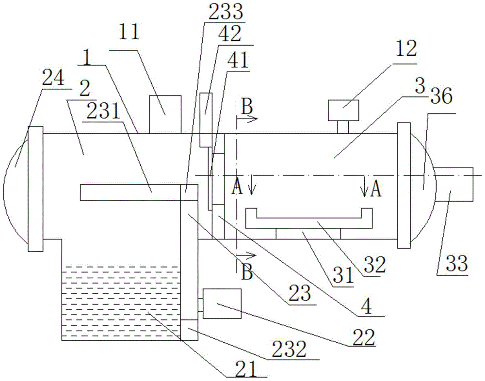
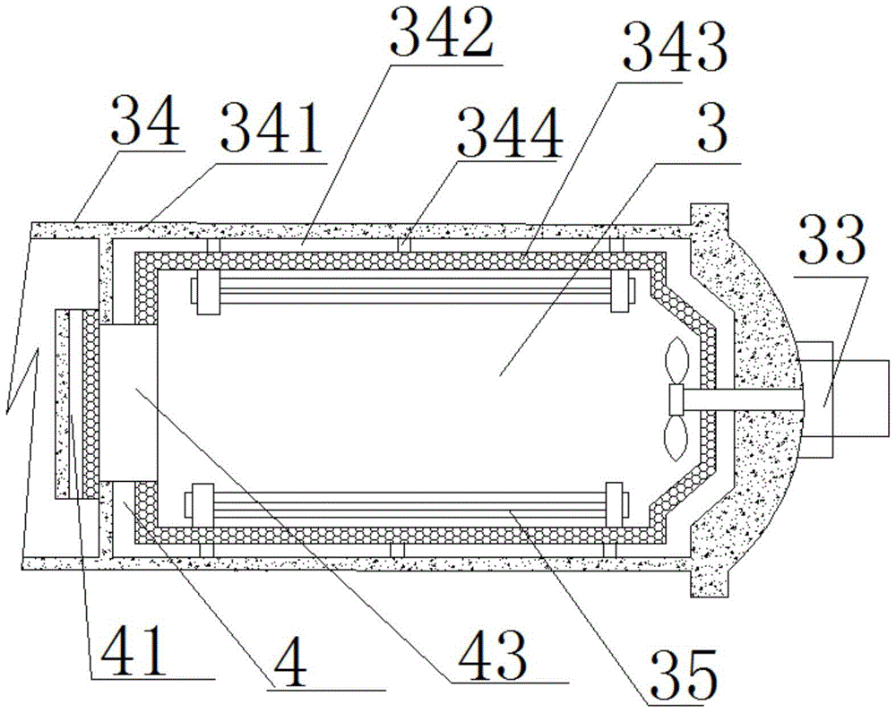
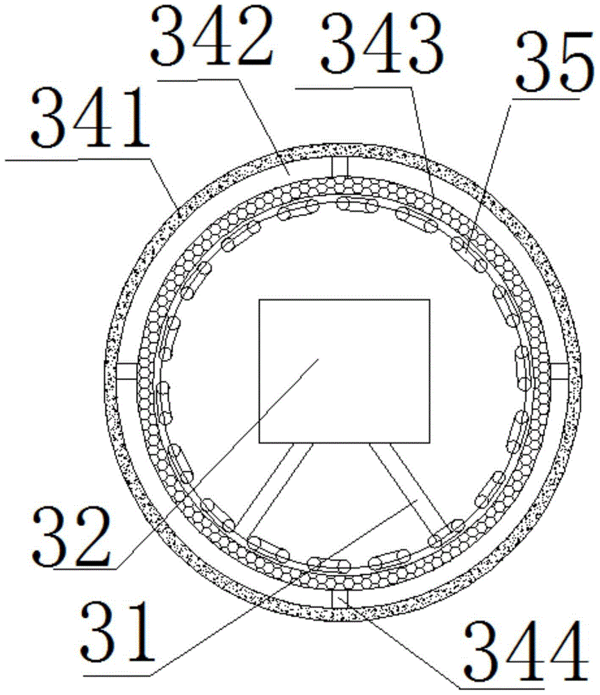
[0025] A kind of vacuum furnace of the present embodiment, such as Figure 1-3 As shown, it includes a furnace shell, and a cooling chamber and a heating chamber are arranged inside the furnace shell, and the cooling chamber and the heating chamber are separated by a partition wall; the cooling chamber is sequentially provided with gas quenching chambers from top to bottom. Chamber and oil quenching chamber, while the upper part of the gas quenching chamber is provided with an inflatable rapid cooling mechanism, while the lower part of the oil quenching chamber is provided with an oil quenching oil tank, and the side of the cooling chamber opposite to the heating chamber is provided with a cooling chamber furnace door; The heating chamber is provided with a heating chamber platform, the material frame is placed on the heating chamber platform, and at the same time, one or more heating tubes are uniformly arranged in the heating chamber along the circumference, and the outside o...


PUM


Abstract

The invention relates to a vacuum furnace, and belongs to the technical field of a vacuum furnace. The vacuum furnace comprises a cooling chamber and a heating chamber, wherein the cooling chamber and the heating chamber are separated through a partition wall; an insulated door is arranged on the partition wall; the cooling chamber comprises an gas quenching chamber and an oil quenching chamber; meanwhile, an air inflation rapid cooling mechanism is arranged at the upper part of the gas quenching chamber while an oil quenching oil bath with a stirrer is formed in the lower part of the oil quenching chamber; a gas convective circulation mechanism is arranged on the heating chamber; each of the heating chamber and the insulated door is orderly provided with an insulated layer, a vacuum layer and a stainless steel housing from inside to the outside of the heating chamber. The vacuum furnace disclosed by the invention is not only safe in oil quenching, and uniform in material heating, but also good in heat insulation effect.

Description

technical field [0001] The invention relates to a vacuum furnace, belonging to the technical field of vacuum furnaces. Background technique [0002] At present, the existing vacuum furnace includes a cooling chamber and a heating chamber, and the cooling chamber and the heating chamber are separated by a partition wall; a gas quenching chamber and an oil quenching chamber are arranged inside the cooling chamber, and the gas quenching chamber is provided with an air-filled quick-cooling mechanism. source, while the oil quenching chamber performs oil quenching through the oil quenching tank. The inside of the heating chamber includes a heating chamber platform and a material frame. The material frame is placed on the heating chamber platform. At the same time, one or more heating tubes are evenly arranged in the heating chamber along the circumferential direction, and a vacuum mechanism is arranged outside the heating chamber. There is an entrance and exit of the compartment ...

Claims


Application Information

Patent Timeline
Patent Type & Authority Patents(China)
IPC IPC(8): C21D1/773
Inventor 李荣华
Owner SUZHOU PULINGDA AUTOMATION TECH CO LTD
Why Eureka
Try Eureka