Steam setting device of steam sock setting machine

A steam setting and setting machine technology, applied in the field of machinery, can solve problems such as high cost, insufficient setting, and unqualified socks quality, and achieve the effects of reducing consumption, saving water resources and production costs, and reducing labor costs

Inactive Publication Date: 2014-04-16
张金英
View PDF6 Cites 9 Cited by
  • Summary
  • Abstract
  • Description
  • Claims
  • Application Information

AI Technical Summary

Problems solved by technology

[0003] At present, steam setting is often carried out in a steam room. By putting socks into the steam room, and then pouring steam into the steam room, a large amount of steam is often required through the above method. When setting the shape, the steam room needs to be filled with steam, and a large amount of steam is required t...

Method used


Image

  • Steam setting device of steam sock setting machine
  • Steam setting device of steam sock setting machine
  • Steam setting device of steam sock setting machine

Examples


Embodiment 1

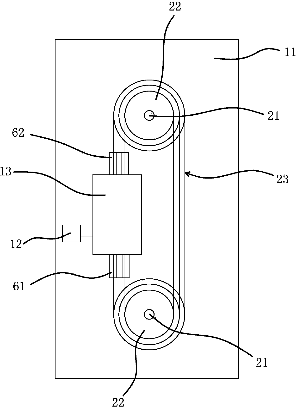
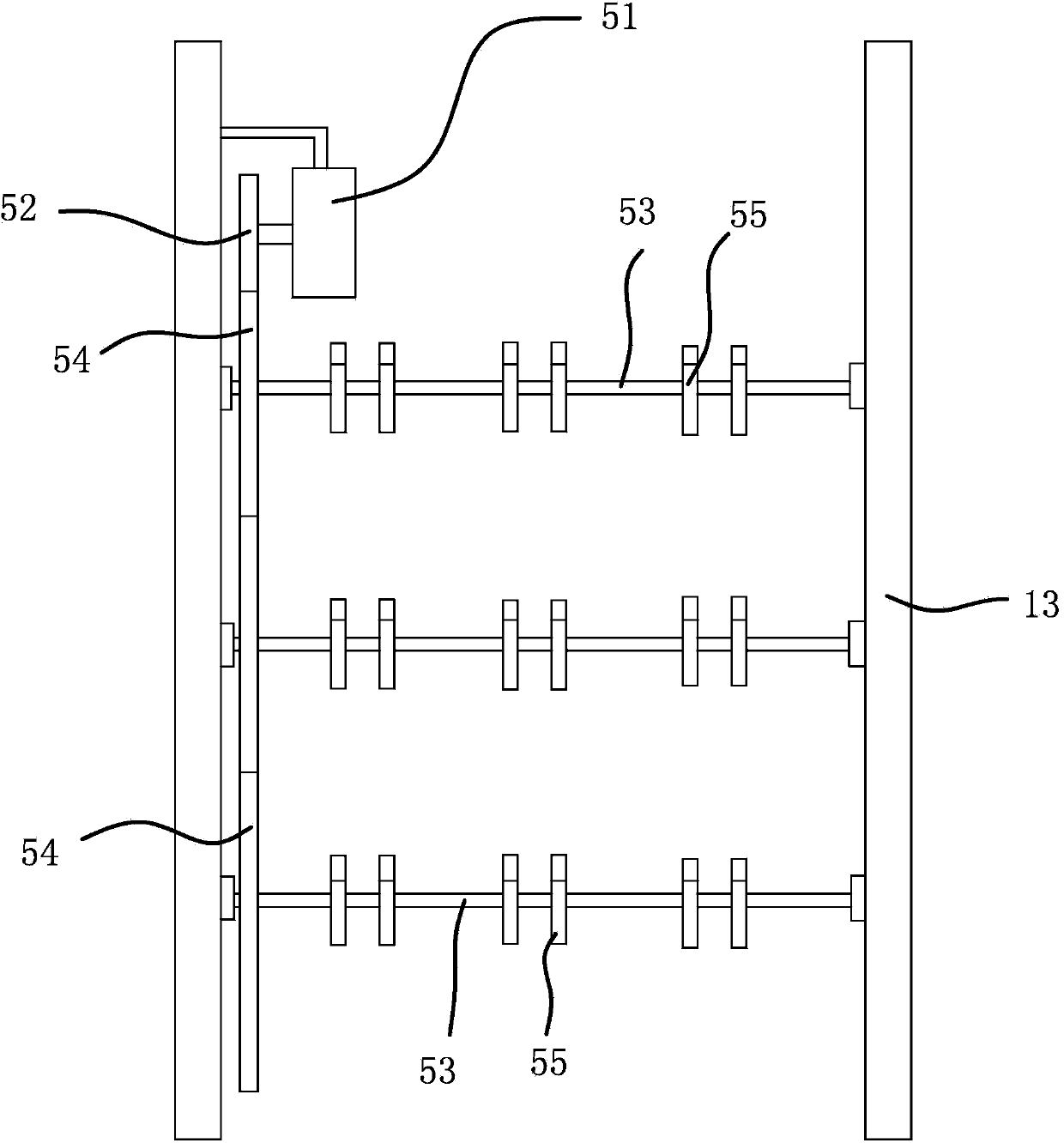
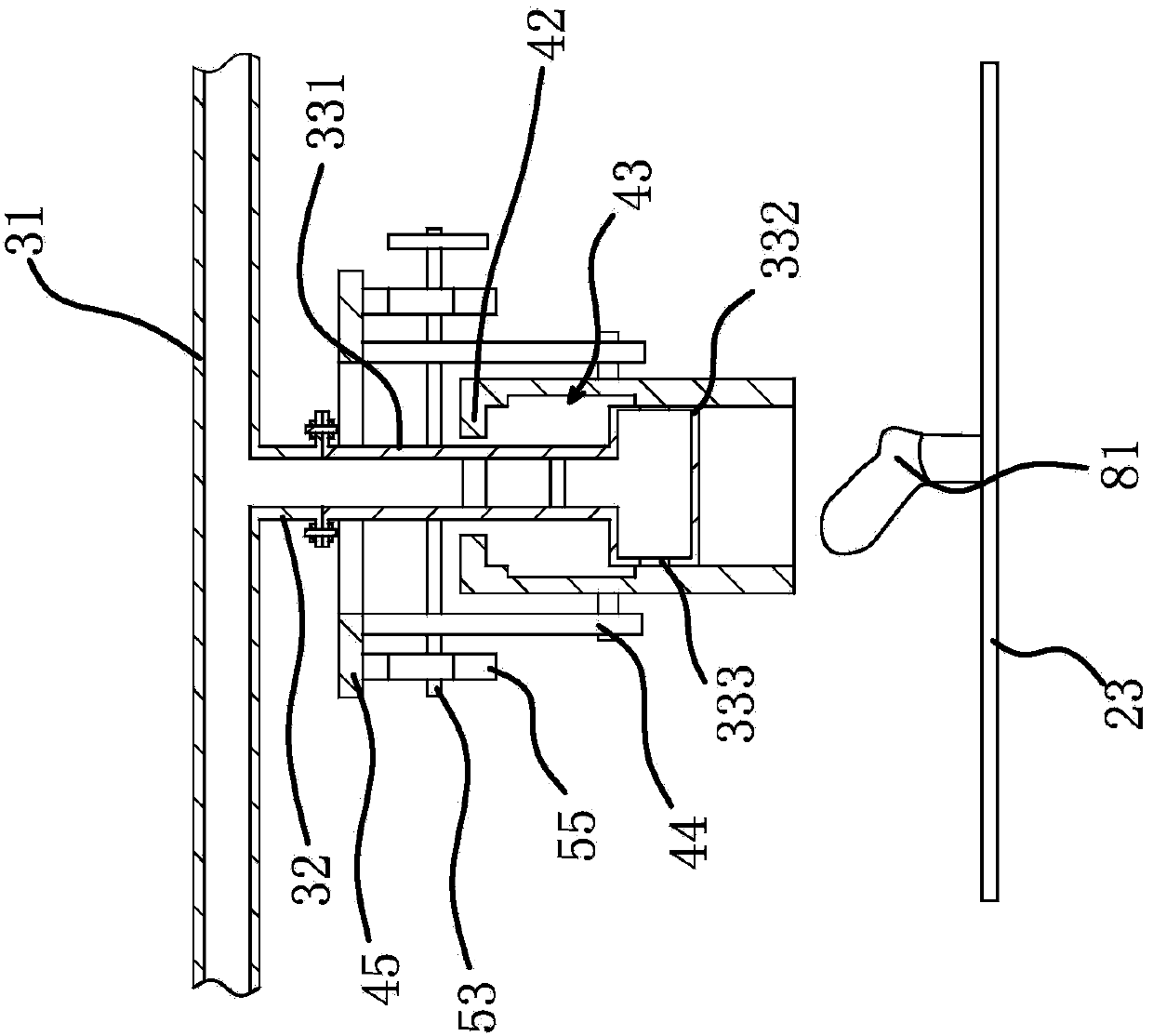
[0022] A steam setting device of a sock steam setting machine, such as figure 1 As shown, the sock steam setting machine includes a frame 11, a steam generator 12, a steam setting chamber 13 and a controller. The steam generator 12 used in the present invention is a prior art and is available on the market. The controller is Single-chip microcomputer; Two driving shafts 21 are connected in rotation on the frame 11, and the driving rotation is driven by a driving motor, and several transmission sprockets 22 are fixed on the driving shaft 21 along its axis successively, and the diameters of the transmission sprockets 22 decrease successively from top to bottom. Small, drive chain 23 is connected with drive chain 23 between the transmission sprockets 22 of equal diameter on the drive shaft 21, one side of drive chain 23 all passes through steam setting chamber 13, and socks cover plate 81 is all fixed on every drive chain 23, The sock cover plates 81 are evenly distributed along ...

Embodiment 2

[0032] The structure and principle of this embodiment are basically the same as that of Embodiment 1. The difference is that the control mechanism includes control cylinder 1, control cylinder 2 and a control rod. Two connecting rods are fixed on the pipe wall of the gas collecting pipe. On both sides of the gas collecting pipe, the upper end of the connecting rod is fixed with a lifting ring. The control cylinder 1 and the control cylinder 2 are fixed on the top of the steam calibrating chamber. The control cylinder 1 and the control cylinder 2 are respectively located at the exit and entrance of the steam calibrating chamber. Main rod 1 fixed by the piston rod of cylinder 1, main rod 2 fixed to the piston rod controlling cylinder 2, and several sub-rods between main rod 1 and main rod 2 corresponding to steam pipelines one by one, sub-rods and steam pipelines Parallel, the sub-rod passes through the suspension ring, and the first control cylinder and the second control cylind...


PUM


Abstract

The invention provides a steam setting device of a steam sock setting machine, belongs to the technical field of machinery and aims to solve the technical problem of setting deficiency and the like of the conventional steam sock setting machine. The steam setting device of the sock steam setting machine comprises steam pipelines and gas collecting tubes, wherein the steam pipelines are fixed in a steam setting chamber and in one-to-one correspondence with driving chain wheels; a plurality of steam sub-pipelines are arranged at the lower ends of the steam pipelines and all fixedly communicated with a connecting pipe; an air outlet part is sleeved with the gas collecting tubes; a control mechanism is arranged between the gas collecting tubes and the steam setting chamber, and can drive the gas collecting tubes to slide up and down to enable the gas collecting tubes to open an air outlet and cover sock sleeve plates or to close the air outlet and enable the gas collecting tubes to be positioned above the sock sleeve plates. The steam setting device has the advantages that a uniform steam sock setting effect is achieved, and the quality of socks is ensured.

Description

technical field [0001] The invention belongs to the technical field of machinery, and relates to a sock steam setting machine, in particular to a steam setting device of the sock steam setting machine. Background technique [0002] After the socks are knitted, they need to be shaped to ensure that the socks always maintain a certain shape after being worn, so as to increase the service life of the socks. Existing stereotyping mainly adopts steam setting to socks, makes the cotton thread setting of socks by steam. [0003] At present, steam setting is often carried out in a steam room. By putting socks into the steam room, and then pouring steam into the steam room, a large amount of steam is often required through the above method. When setting the shape, the steam room needs to be filled with steam, and a large amount of steam is required to generate steam. Therefore, high costs need to be paid for the generation of steam; since the steam in the steam chamber is in a float...

Claims


Application Information

Patent Timeline
IPC IPC(8): D06C5/00D06B19/00
Inventor 吴伟东
Owner 张金英
Why Eureka
Try Eureka