Supercharge Your Innovation With Domain-Expert AI Agents!

Thermal energy recycling heat exchanger

A heat recovery and heat exchanger technology, applied in heat exchange equipment, heat transfer modification, lighting and heating equipment, etc., can solve problems such as poor heat exchange effect and slow heat exchange speed

Active Publication Date: 2014-04-16
CHENGDU HENGRUN HIGH NEW SCI & TECH
View PDF5 Cites 0 Cited by
  • Summary
  • Abstract
  • Description
  • Claims
  • Application Information

AI Technical Summary

Problems solved by technology

[0006] However, the heat recovery heat exchanger in the prior art has a slow heat transfer rate and poor heat transfer effect
In addition, since waste water usually contains more impurities, it is easy to adhere to the heat exchange device 2, and the impurities have the effect of heat insulation, which leads to poor heat exchange effect
[0007] Therefore, how to increase the heat exchange speed of the heat recovery heat exchanger and prevent impurities from adhering to the heat exchange device, resulting in poor heat exchange effect, has become an important technical problem to be solved by those skilled in the art.

Method used


Image

  • Thermal energy recycling heat exchanger
  • Thermal energy recycling heat exchanger

Examples


Embodiment Construction

[0022] The specific embodiment provides a heat recovery heat exchanger, which has a fast heat exchange speed and can avoid the problem that impurities are attached to the heat exchange device and affect the heat exchange efficiency.

[0023] The following will clearly and completely describe the technical solutions in the embodiments of the present invention with reference to the accompanying drawings in the embodiments of the present invention. Obviously, the described embodiments are only some, not all, embodiments of the present invention. Based on the embodiments of the present invention, all other embodiments obtained by persons of ordinary skill in the art without making creative efforts belong to the protection scope of the present invention.

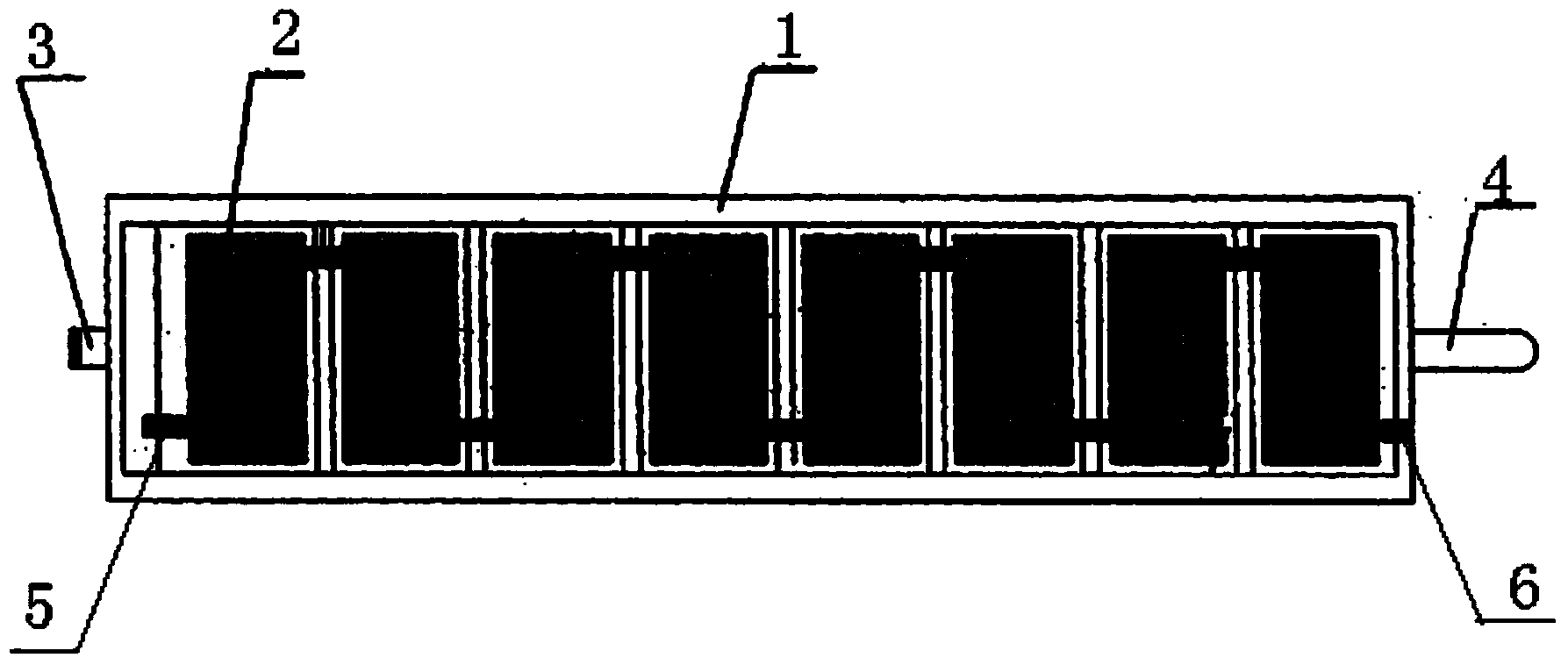
[0024] A heat recovery heat exchanger provided in this specific embodiment includes a waste water tank, at least one side wall of the waste water tank is provided with an opening, the opening is sealed and covered with an elastic ...


PUM


Abstract

The invention discloses a thermal energy recycling heat exchanger. The thermal energy recycling heat exchanger comprises a waste heat water tank body with at least one side wall provided with an opening sealed with an elastic film. The thermal energy recycling heat exchanger further comprises a drive device used for driving the elastic film to repeatedly deform. The provided thermal energy recycling heat exchanger is high in heat exchanging speed and capable of solving the problem that due to the fact that impurities are attached to a heat exchanging device, the heat exchanging efficiency is affected.

Description

technical field [0001] The invention relates to the technical field of heat energy recovery, in particular to a heat energy recovery heat exchanger. Background technique [0002] During the printing and dyeing process, most fabrics require high-temperature and high-pressure dyeing. The dyeing temperature is between 100-135°C. After high-temperature dyeing of fabrics, some high-temperature wastewater with a temperature above 95°C will be formed. In order to reduce pollution, the factory will After the high-temperature wastewater is purified and treated, it can be recycled. [0003] Before purifying the high-temperature wastewater, it is necessary to cool down the high-temperature wastewater. There is a heat recovery heat exchanger in the prior art, which can transfer the heat energy in the high-temperature wastewater to clean cold water, so as to realize the recycling of heat energy. At the same time, It can quickly cool down the high-temperature wastewater to facilitate the...

Claims


Application Information

Patent Timeline
IPC IPC(8): F28F13/06
Inventor 赵旭李芮岚
Owner CHENGDU HENGRUN HIGH NEW SCI & TECH
Features
  • R&D
  • Intellectual Property
  • Life Sciences
  • Materials
  • Tech Scout
  • Unparalleled Data Quality
  • Higher Quality Content
  • 60% Fewer Hallucinations
Learn More