Counter shaft of viscosity meter

A technology of counters and viscometers, applied in instruments, scientific instruments, flow characteristics, etc., can solve the problems of unstable work of viscometers, affecting product quality, unreasonable structure, etc., to achieve reasonable structure, meet production needs, and design correct. Effect

Inactive Publication Date: 2014-04-16
PINGHU YONGGUANG MACHINERY PARTS
View PDF4 Cites 0 Cited by
  • Summary
  • Abstract
  • Description
  • Claims
  • Application Information

AI Technical Summary

Problems solved by technology

[0004] In order to overcome the defects of the counter shaft of the ordinary viscosity machine, such as unstable operation, inaccurate measurement, large errors, and influence on product quality caused by wrong design and unreasonable structure, the present invention provides a counter shaft of the viscosity machine, the viscosity machine The counter shaft is an important part of the viscosity machine. The correct design and reasonable structure can make the viscosity machine work stably, ensuring accurate measurement, stable performance, high precision, and detection in place.

Method used


Image

  • Counter shaft of viscosity meter
  • Counter shaft of viscosity meter
  • Counter shaft of viscosity meter

Examples


Embodiment Construction

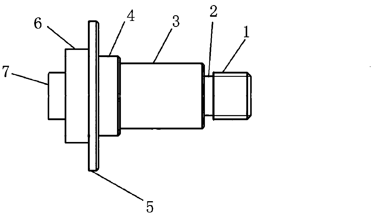
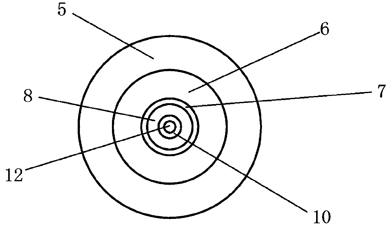
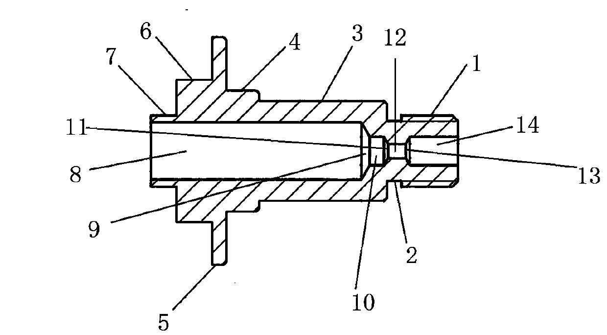
[0011] The present invention will be further described below in conjunction with accompanying drawing:

[0012] A counter shaft of a viscosity machine, including a shaft body and a round hole, characterized in that the shaft body is from right to left in turn from the right end to the first shaft 1, the second shaft 2, the third shaft 3, the fourth shaft 4, and the fifth shaft 5. The sixth axis 6 and the seventh axis 7 at the left end are conjoined. They are all the same axis circle; the seventh axis 7 at the left end is in the shape of a cylinder and placed horizontally. The diameter of the outer circumference of the seventh axis 7 at the left end of the axis body is 5㎜, the length of left and right is 1.8㎜; the right circular surface of the seventh axis 7 at the left end of the shaft body is connected with the left circular surface of the sixth axis 6; the sixth axis 6 is in the shape of a cylinder and placed horizontally, and the sixth axis The diameter of the outer circumf...


PUM

PropertyMeasurementUnit
diameteraaaaaaaaaa
diameteraaaaaaaaaa

Abstract

The invention discloses a counter shaft of a viscosity meter. The counter shaft comprises a shaft body, wherein the shaft body is formed by connection of a right end first shaft, a second shaft, a third shaft, a fourth shaft, a fifth shaft, a sixth shaft and a left end seventh shaft sequentially from right to left; the right end first shaft, the second shaft, the third shaft, the fourth shaft, the fifth shaft, the sixth shaft and the left end seventh shaft are concentric, cylindrical and arranged transversely; circumferential edges of right round surfaces of the fifth shaft, the fourth shaft and the third shaft are turned into circles of chamfer angles of 45 degrees respectively; an outer circumferential edge of the first shaft is turned into a circle of outer thread, and a circumferential edge of a right round surface of the first shaft is turned into a circle of chamfer angle of 45 degrees; a first round hole, a first conical hole, a second round hole, a second conical hole, a third round hole, a third conical hole and a fourth round hole are drilled rightwards in the middle of a left round surface of the left end seventh shaft of the shaft body sequentially, are concentric and form a through hole penetrating through the right round surface of the right end first shaft of the shaft body from the left round surface of the left end seventh shaft of the shaft body; and the counter shaft of the viscosity meter is made of a steel material for shafts.

Description

[0001] technical field [0002] The invention relates to a counter shaft of a viscosity machine, in particular to an important part of a new instrument for measuring the viscous resistance of a liquid and the absolute viscosity of a liquid—a viscosity machine. Background technique [0003] Viscometer is widely used to measure the viscosity of oil, paint, food, medicine, adhesive and other fluids. Usually, it is required to measure the viscosity of various fluids in order to understand, grasp and improve the quality of the product, and to achieve this purpose, it is most necessary to complete the measurement with a viscosity machine with good performance. The existing viscosity machines are imported and expensive; some of the domestic ones have large errors, are inconvenient to use, and fail to achieve the purpose; our company has innovated and manufactured a new, practical and low-cost new type of viscometer in years of research and experiments. The viscosity machine has...

Claims


Application Information

Patent Timeline
Patent Type & Authority Applications(China)
IPC IPC(8): G01N11/00
Inventor 柯根祥
Owner PINGHU YONGGUANG MACHINERY PARTS
Why Eureka
Try Eureka