Spacecraft relative orbit control method

A relative orbit and control method technology, applied in the field of short-distance relative orbit control, can solve problems such as difficulty in maintaining time, low pointing accuracy, and easy identity exposure, and achieve the effect of improving task accuracy, simple analysis ideas, and not easy to expose identity

Active Publication Date: 2014-04-16
HARBIN INST OF TECH
View PDF2 Cites 59 Cited by
  • Summary
  • Abstract
  • Description
  • Claims
  • Application Information

AI Technical Summary

Problems solved by technology

[0004] The present invention provides a method for controlling the relative orbit of a spacecraft to realize the skimming mode of the spacecraft, that is, the tracking spacecraft operates according to its own orbit after entering a specified space range related to the target spacecraft, and only needs to perform attitude control; thereby Overcome the problems of complex calculations, low pointing accuracy due to attitude-orbit control coupling, easy exposure of identity, and difficulty in maintaining time in traditional methods such as hovering, accompanying flight, and flying around

Method used


Image

  • Spacecraft relative orbit control method
  • Spacecraft relative orbit control method
  • Spacecraft relative orbit control method

Examples


specific Embodiment approach 1

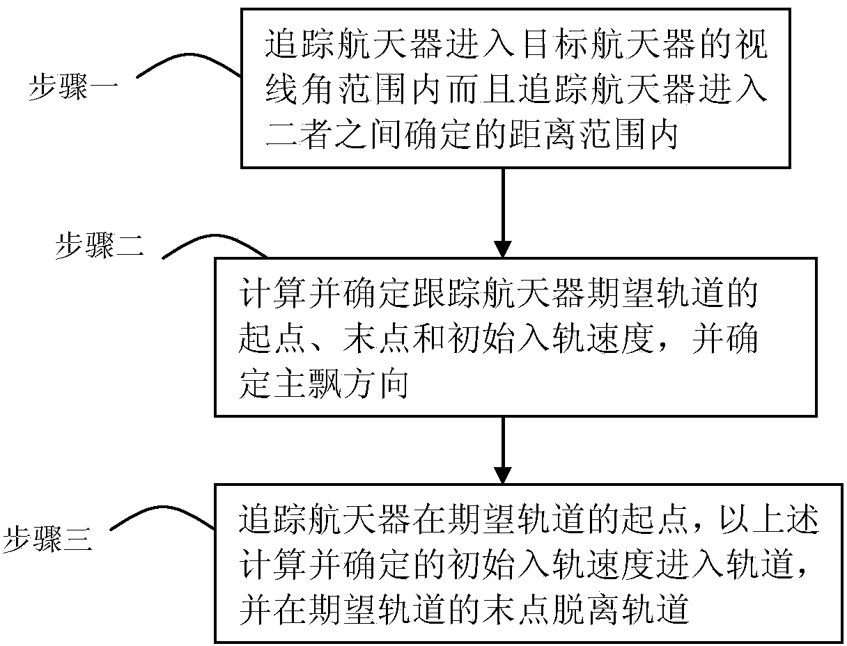
[0008] Specific implementation mode one: the following combination figure 1 This embodiment will be specifically described. This embodiment is realized through the following steps: 1. The tracking spacecraft enters the line-of-sight range of the target spacecraft and the tracking spacecraft enters the distance range determined between the two; 2. Calculate and determine the starting point of the expected orbit of the tracking spacecraft , the end point and the initial orbital velocity, and determine the main drift direction; 3. Track the spacecraft at the starting point of the desired orbit, enter the orbit at the initial orbital velocity calculated and determined above, and leave the orbit at the end point of the desired orbit, so that Complete the skimming maneuver of the target spacecraft.

[0009] (1) Explanation and customization of related concepts:

[0010] Geocentric inertial coordinate system (O-XYZ): The coordinate origin O is at the earth's barycenter, the Z-axis ...

specific Embodiment

[0267] Specific embodiments: the following is an algorithm simulation verification experiment.

[0268] (1) Simulation parameters

[0269] 1.1 Target star orbit parameters

[0270] The target star is in the GEO orbit, and the hexagram of the initial orbit is: a 1 =4.225×10 7 m, e 1 =0, i 1 =5°,Ω 1 =31°, ω 1 =0°, M0 1 =0°.

[0271] Satellite perturbation coefficient parameters

[0272] Aerodynamic coefficient C D =1, drag coefficient C d =2.2, reflection coefficient C r =0.8.

[0273] 1.2 Skimming parameters

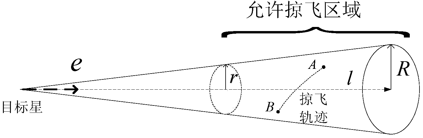
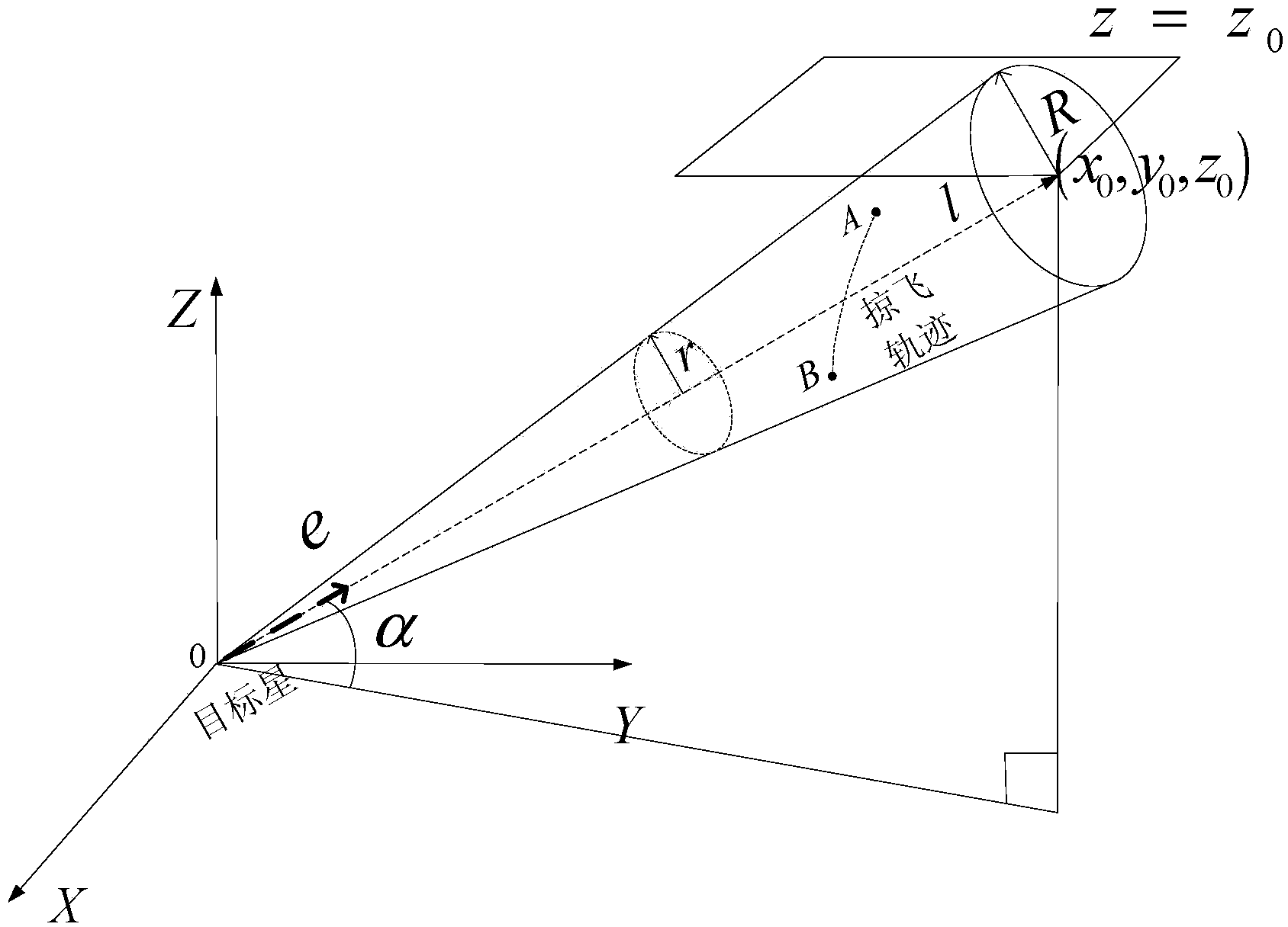
[0274] Target star line of sight direction vector e -hill =[-49647;-5194;2863], the minimum distance R of the tracking star in the line of sight direction of the target star min =50km, the farthest distance is R max =99.2km, sight angle θ=0.35°. The expected fly-by time is designed around 800s.

[0275] (2) Skimming trajectory design

[0276] Firstly, according to the design idea of ​​section 0, the main drift direction is given as the y direction. Reg...


PUM


Abstract

The invention relates to a spacecraft relative orbit control method which relates to a spacecraft close range relative orbit control method to achieve a hedgehop flying mode of a spacecraft, namely a tracking spacecraft runs according to the self orbit after entering the designated space range relevant to a target spacecraft, and only gesture control is required. The problems of complex calculation, poor pointing accuracy caused by pose orbit control coupling, easiness in identity exposure, difficulty in time maintaining and the like in the traditional methods of hovering, accompanying flying, diversion and the like are solved. The method includes the following steps that 1 the tracking spacecraft enters a sight angle range of the target spacecraft and enters the determined distance range between the tracking spacecraft and the target spacecraft; 2 the starting point, the end point and the initial orbit entering speed of an expected orbit of the target spacecraft are calculated, and the main wave direction is determined; 3 the tracking spacecraft enters the orbit with the calculated determined initial orbit entering speed from the starting point of the expected orbit and breaks away from the orbit at the end point of the expected orbit.

Description

technical field [0001] The invention relates to a short-distance relative orbit control method of a spacecraft. Background technique [0002] One of the important research hotspots in today's aerospace field is the short-distance relative orbital motion control of spacecraft. The relative orbital motion of spacecraft is to study the continuous motion law of a spacecraft (tracking spacecraft) around another spacecraft (target spacecraft). It is often applied to space missions such as formation flight, on-orbit maintenance, rendezvous and docking, tracking and monitoring. At present, the most commonly used forms of relative orbital motion are hovering (the tracking spacecraft maintains the relative position of the target spacecraft), accompanying flight (the tracking spacecraft flies around a point near the target spacecraft in a closed trajectory) and flying around (accompanied flight A special case of , where the center of the closed trajectory is the target spacecraft), e...

Claims


Application Information

Patent Timeline
Patent Type & Authority Applications(China)
IPC IPC(8): G05D1/10
Inventor 孙延超马广富凌惠祥李传江赵文锐李程
Owner HARBIN INST OF TECH
Why Eureka
Try Eureka