
Three-dimensional model dynamic display method and device

A 3D model and dynamic display technology, applied in image data processing, 3D image processing, instruments, etc., can solve the problem that there is no separate component drive, 3D graphics effect cannot be realized, and 3D (3D) mechanism model cannot be read and displayed, etc. problems, to achieve the effect of improving development efficiency

Inactive Publication Date: 2014-04-16
HUNAN SANY INTELLIGENT CONTROL EQUIP
View PDF4 Cites 3 Cited by
  • Summary
  • Abstract
  • Description
  • Claims
  • Application Information

AI Technical Summary

Problems solved by technology

[0002] At present, when the display recognition module is performing graphic display, it can only display static pictures. The display of dynamic graphics needs to be directly driven by changing data sources, and it is impossible to read and display three-dimensional (3D) mechanism models.
Although the existing computer-aided design (CAD, Computer Aided Design) software provides model editing and driving motors to drive the model for simulation, it does not have the function of driving individual components, nor does it provide external devices for driving interfaces
[0003] In addition, the graphics library provided by the software itself, such as text boxes, curve boxes, picture boxes, etc., is used for display. Although some properties of graphic controls can be associated with external devices for dynamic display, there is no display recognition module that supports importing 3D models for dynamic display. 3D Graphics Features
However, the use of combined controls for complex graphics or dynamic display is simply superimposed on flat graphics, and 3D graphics effects cannot be achieved.

Method used


Image

  • Three-dimensional model dynamic display method and device
  • Three-dimensional model dynamic display method and device

Examples


Embodiment Construction

[0023] The following will clearly and completely describe the technical solutions in the embodiments of the present invention with reference to the accompanying drawings in the embodiments of the present invention. Obviously, the described embodiments are only some, not all, embodiments of the present invention. Based on the embodiments of the present invention, all other embodiments obtained by persons of ordinary skill in the art without creative efforts fall within the protection scope of the present invention.

[0024] It should be noted that, in the case of no conflict, the embodiments of the present invention and the features in the embodiments can be combined with each other.

[0025] The basic idea of ​​the present invention is: Aiming at the technical problems existing in the prior art, a dynamic model display method and device are proposed. Parameter data description points, all added parameter points are imported into the display identification module, and displayed...


PUM


Abstract

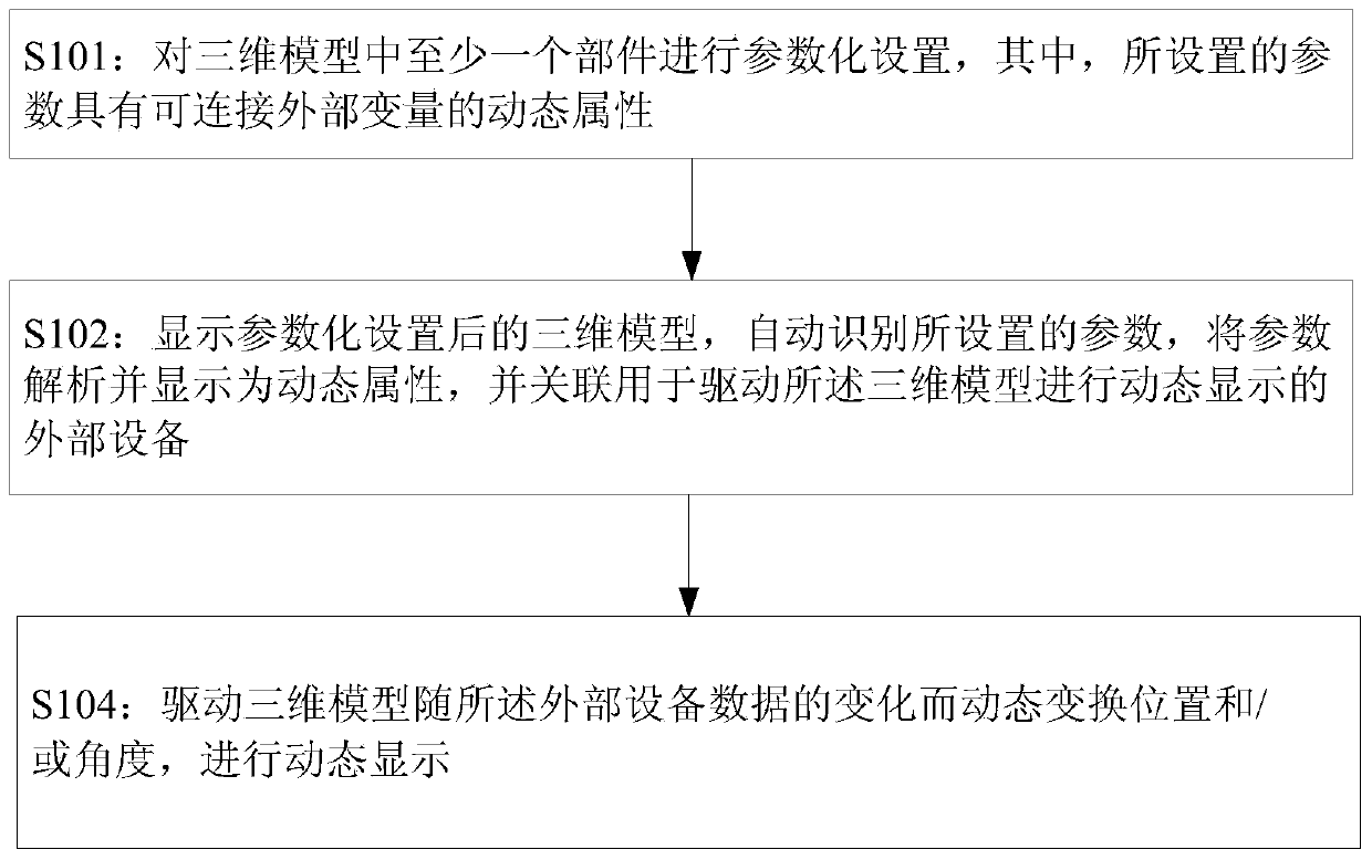
The invention discloses a three-dimensional model dynamic display method and device. The three-dimensional model dynamic display method includes the steps that at least one part in a three-dimensional model is parameterized, wherein set parameters have dynamic properties which make the set parameters capable of being connected with external variables; the three-dimensional model of which the parameters are set is displayed, the set parameters are recognized, analyzed and displayed to be the dynamic properties, and external equipment used for driving the three-dimensional model to be dynamically displayed is associated; positions and / or angles of the three-dimensional model are dynamically changed along with the change of data of the external equipment, and the three-dimensional model is dynamically displayed. Consequently, according to the three-dimensional model dynamic display method and device, the static three-dimensional model structure can be dynamically displayed, and development efficiency is improved.

Description

technical field [0001] The invention relates to the field of engineering machinery, in particular to a method and device for dynamic display of a three-dimensional model. Background technique [0002] At present, the display recognition module can only display static pictures when performing graphic display, and the display of dynamic graphics needs to be directly driven by changing data sources, and cannot read and display three-dimensional (3D) mechanism models. Although the existing computer-aided design (CAD, Computer Aided Design) software provides model editing and driving motors to drive models for simulation, it does not have the function of driving individual components, nor does it provide external devices for driving interfaces. [0003] In addition, the graphics library provided by the software itself, such as text boxes, curve boxes, picture boxes, etc., is used for display. Although some properties of graphic controls can be associated with external devices for...

Claims


Application Information

Patent Timeline
IPC IPC(8): G06T19/00
CPCG06T15/00
Inventor 周翔盛四华熊俊
Owner HUNAN SANY INTELLIGENT CONTROL EQUIP
Learn More