
A Miniaturized Temperature and Stress Controllable Magnetoelectric Transducer

A magnetoelectric transducer, stress technology, applied in piezoelectric effect/electrostrictive or magnetostrictive motors, electrical components, generators/motors, etc., can solve the problem of limited use range, temperature control and force control Inconvenient, complex devices and other problems, to achieve the effect of magnetoelectric conversion capability, strong magnetoelectric coupling strength, and increase or decrease

Inactive Publication Date: 2016-08-17
CHINA JILIANG UNIV
View PDF2 Cites 0 Cited by
  • Summary
  • Abstract
  • Description
  • Claims
  • Application Information

AI Technical Summary

Problems solved by technology

[0004] The purpose of the present invention is to provide a miniaturized temperature and stress controllable magnetoelectric transducer, which not only has a simple structure, but also has a large volume. Small, easy to use, and small error in use, with the advantages of controllable temperature and stress

Method used


Image

  • A Miniaturized Temperature and Stress Controllable Magnetoelectric Transducer
  • A Miniaturized Temperature and Stress Controllable Magnetoelectric Transducer
  • A Miniaturized Temperature and Stress Controllable Magnetoelectric Transducer

Examples


Embodiment 1

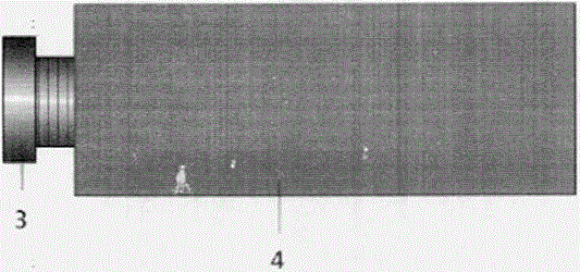
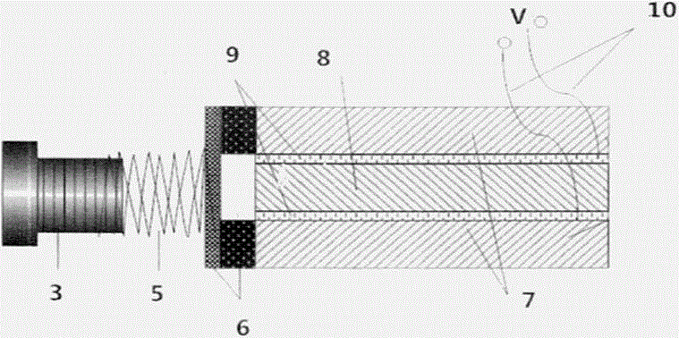
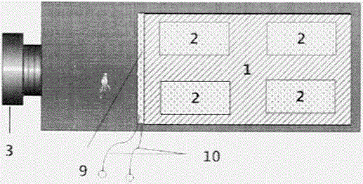
[0035] The miniaturized temperature and stress controllable magnetoelectric transducer of the present invention comprises: magnetoelectric composite structure 1, encapsulation shell 4 that antimagnetic material is made, antimagnetic screw 3, antimagnetic piston 6 and place on the upper surface of magnetoelectric composite structure 1 A plurality of semiconductor temperature control sheets 2; the magnetoelectric composite structure 1 is a laminated composite structure formed by laminating and bonding two sheets of giant magnetostrictive material 7 and a piece of piezoelectric material 8. The piezoelectric material 8 is a PZT material, super The magnetostrictive material 7 is a Terfenol-D material, which is rectangular in shape, and the layers are bonded by epoxy resin, and the magnetoelectric composite structure 1 is fixed on the bottom surface of the package shell 4 by epoxy resin; the package shell 4 There is an opening on one side surface and an antimagnetic screw 3 is provid...


PUM


Abstract

The invention discloses a miniaturized magneto-electricity energy converter with controllable temperature and controllable stress. The miniaturized magneto-electricity energy converter with the controllable temperature and the controllable stress comprises a magneto-electricity composite structure, an encapsulation shell, an antimagnetic screw, an antimagnetic piston and a plurality of semiconductor temperature control sheets which are arranged on the upper surface of the magneto-electricity composite structure. The magneto-electricity composite structure is a laminated composite structure composed of two pieces of giant magnetostrictive material and a piece of piezoelectric material in a laminated adhesion mode, wherein the piezoelectric material layer is clamped between the two pieces of giant magnetostrictive material. A hole is formed in one side surface of the encapsulation shell and the antimagnetic screw is placed in the hole. The antimagnetic piston makes contact with the upper piece of giant magnetostrictive material and the lower piece of giant magnetostrictive material of the magneto-electricity composite structure, and the antimagnetic piston and the piezoelectric material are arranged in the encapsulation shell in a spaced mode. An antimagnetic spring is arranged between the antimagnetic screw and the antimagnetic piston. A groove is formed in the side face, making contact with the giant magnetostrictive material, of the antimagnetic piston, and one end of the piezoelectric material is arranged in the groove. The upper face and the lower face of the piezoelectric material are coated with metal films serving as electrodes. The metal films are connected with an electrode line. The miniaturized magneto-electricity energy converter with the controllable temperature and the controllable stress has the advantages that the structure is simple, the size is small, use is easy, the use error is small, and the temperature and the pressure are controllable.

Description

technical field [0001] The invention relates to energy conversion technology, in particular to a miniaturized magnetoelectric transducer with controllable temperature and stress. Background technique [0002] Magnetoelectric laminated materials have the characteristics of strong magnetoelectric effect and easy preparation, and are widely used in precision control systems, intelligent filters, drives, sensors, transducers, etc., to promote the development of cutting-edge technology, military technology and traditional industries. modernization. With the rapid development of modern high-tech industries, the demand for high-performance and miniaturized magnetoelectric devices based on magnetoelectric composite materials is increasing. [0003] The working principle of magnetoelectric devices composed of magnetoelectric laminated materials is mainly based on the magnetostrictive effect of giant magnetostrictive materials and the piezoelectric effect of piezoelectric materials. ...

Claims


Application Information

Patent Timeline
Patent Type & Authority Patents(China)
IPC IPC(8): H02N2/18
Inventor 周浩淼廉靖崔晓乐
Owner CHINA JILIANG UNIV
Learn More