Improved energy modulator

An energy regulation and energy technology, which is applied in the adjustment value correction device to determine the correction value field, and can solve problems such as disadvantage and inaccuracy

Active Publication Date: 2014-04-16
GSI重离子研究亥姆霍茨中心有限公司
View PDF4 Cites 2 Cited by
  • Summary
  • Abstract
  • Description
  • Claims
  • Application Information

AI Technical Summary

Problems solved by technology

However, the following problem often arises in practice: the body to be irradiated or a part of the body to be irradiated (in particular the region of the target volume to be irradiated) can move
This leads to corresponding inaccuracies in the machining process or handling and is therefore disadvantageous

Method used


Image

  • Improved energy modulator
  • Improved energy modulator
  • Improved energy modulator

Examples


Embodiment Construction

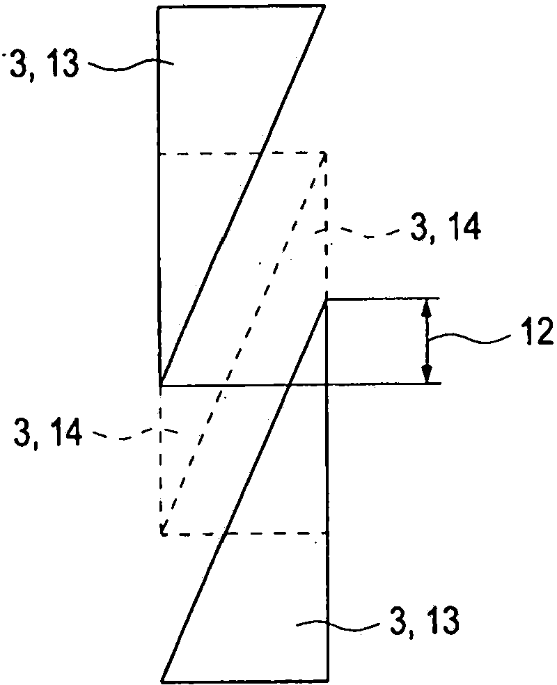
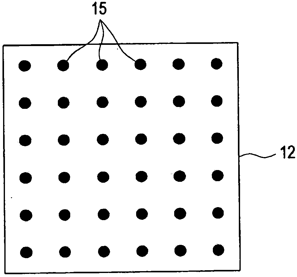
[0035] exist figure 1 A schematic perspective schematic diagram of the energy modulator 1 together with its main components is shown in . The energy modulator 1 serves to attenuate (energy absorb; decelerate) the particle beam 2 passing through the energy modulator 1 to varying degrees. The actual attenuation of the particle beam 2 takes place in the present two wedges 3 arranged point-symmetrically to one another. The two wedges 3 are made of an energy-absorbing material with the best possible material homogeneity. In practice, however, it is difficult to avoid material inhomogeneities and / or surface inhomogeneities (shape inhomogeneities) during the production of the wedge 3 . This results in (initial) irregular fluctuations during the decay of the particle beam 2 passing through the energy modulator 1 . A typical material for wedge 3 is Plexiglass. In principle, however, other materials can also be used for this purpose.

[0036] The two wedges 3 are each fixed on a ho...


PUM


Abstract

The invention relates to a particle energy adjustment system (1) for variably changing the energy of a particle beam (2, 10). The particle energy adjustment system (1) is provided with a variable energy variation device (8) having a control value correction unit (7) for correcting a supplied control value (11). The control value correction unit (7) corrects the supplied control values (11) using previously determined calibration data (15).

Description

technical field [0001] The invention relates to a particle energy regulating device for variably varying the energy of particles of a particle beam passing through the particle energy regulating device, the particle energy regulating device having at least one variable energy changing device. Furthermore, the invention relates to a control value correction device for a particle energy regulation device for variably varying the energy of particles of a particle beam passing through the particle energy regulation device. Finally, the invention also relates to a method for determining a correction value, in particular for a particle energy regulation device and / or for a correction value correction device of the type described above. Background technique [0002] Irradiation of objects is carried out in different technical fields during this time. Depending on the specific application requirements, different types of irradiation methods and different types of radiation are used...

Claims


Application Information

Patent Timeline
Patent Type & Authority Applications(China)
IPC IPC(8): A61N5/10
CPCA61N2005/1087A61N5/1043A61N2005/1095A61N5/1075G21K1/10A61N5/1048G21K1/00
Inventor N·塞图C·贝尔特E·里策尔
Owner GSI重离子研究亥姆霍茨中心有限公司
Why Eureka
Try Eureka