Crimping structure for metal materials, and bus bar using said crimping structure

A technology for riveting structures and metal parts, which is applied to structural parts, riveting connections, and electrical component connections. It can solve problems such as resistance, electrical conversion efficiency and durability, and high resistance of bus bars. Effect of suppressing variation in resistance and improving conductivity

Active Publication Date: 2014-04-16
SANCALL
View PDF6 Cites 10 Cited by
  • Summary
  • Abstract
  • Description
  • Claims
  • Application Information

AI Technical Summary

Problems solved by technology

In this way, to form a battery module, a plurality of bus bars are used depending on the number of battery cells combined, so the resistance of the bus bars themselves also becomes high.
Also, as mentioned above, the bus bars used in lithium-ion batteries, which are widely used in hybrid vehicles and electric vehicles, etc., are formed by combining conductive members made of different types of metal materials on a metal plate, Therefore, the resistance of the joint part cannot be ignored, which affects the power conversion efficiency and durability

Method used


Image

  • Crimping structure for metal materials, and bus bar using said crimping structure
  • Crimping structure for metal materials, and bus bar using said crimping structure
  • Crimping structure for metal materials, and bus bar using said crimping structure

Examples


Embodiment Construction

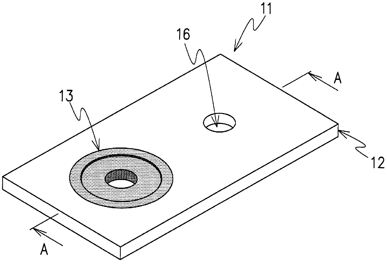
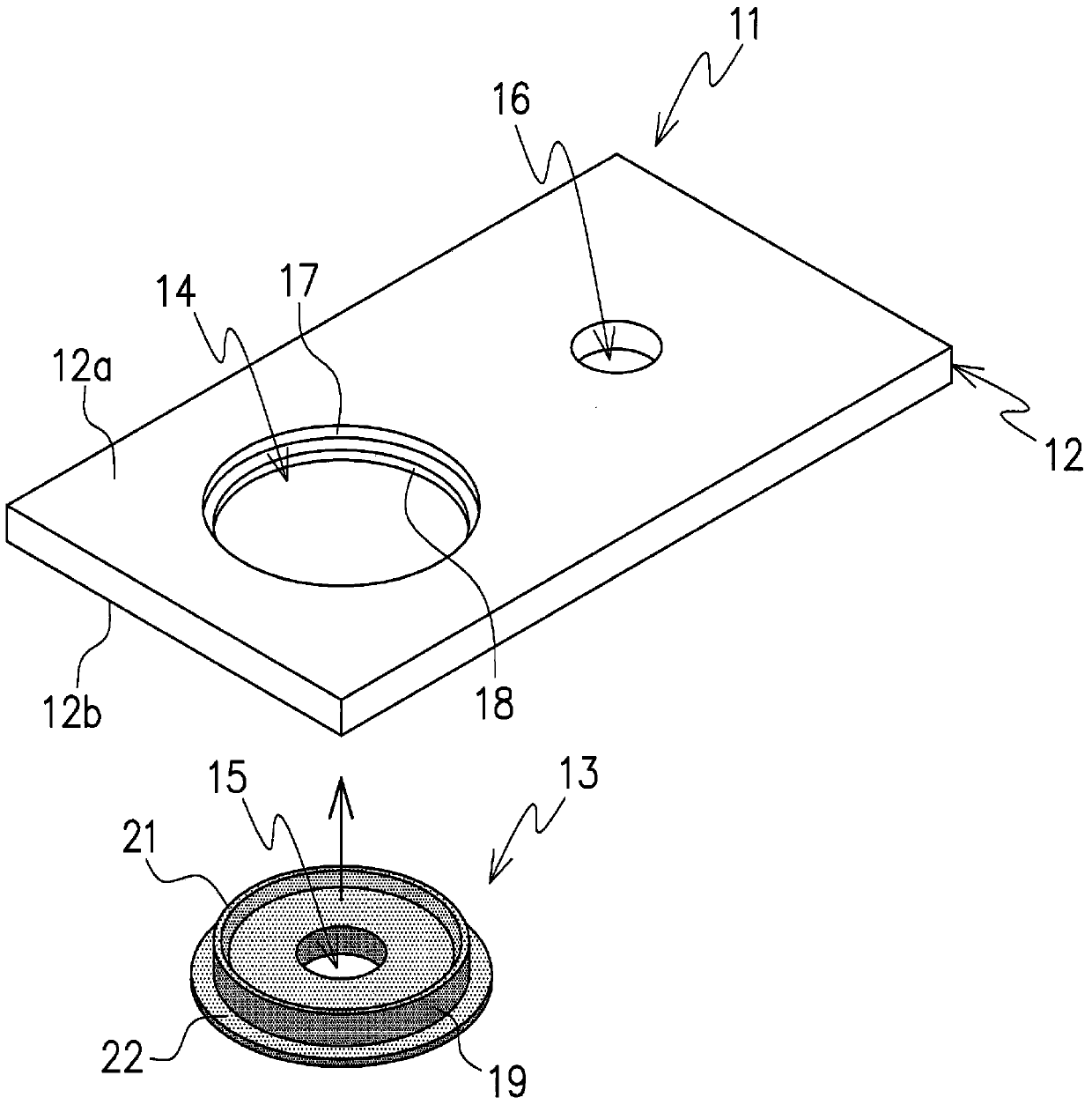
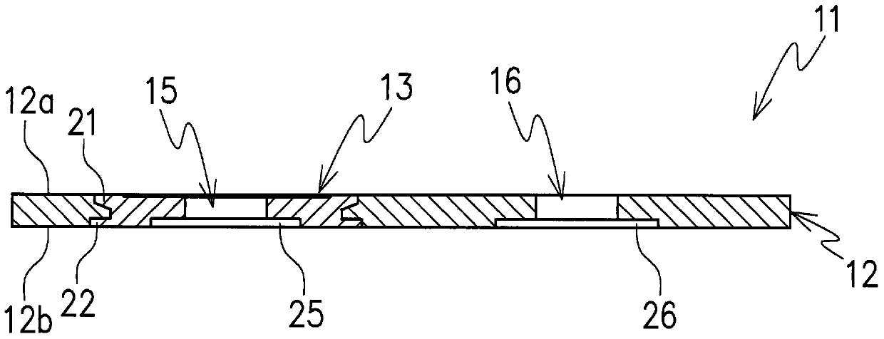
[0029] Hereinafter, embodiments of a riveting structure of a metal member according to the present invention and a bus bar using the riveting structure will be described in detail based on the drawings. figure 1 It is the appearance shape of the bus bar 11 formed using the riveting structure of the present invention, Figure 2 to Figure 7 The form of the caulking structure portion of the bus bar 11 described above is shown. In the caulking structure of the present invention, a disc-shaped conductive member 13 formed of a second metal material is fitted into and fixed to a flat metal plate 12 formed of a first metal material.

[0030] like figure 2 and image 3 As shown, the metal plate 12 is formed in a flat plate shape from a copper material as a first metal member, and has a first hole 14 opened at a predetermined position. The conductive member 13 is formed into a disc shape that can be inserted into the hole 14 by an aluminum material as a second metal piece, and the c...


PUM


Abstract

To provide a crimping structure for metal materials, wherein it is possible to stably and tightly join metal materials and to reduce the electrical resistance even when the joined metal materials are formed from different materials. A crimping structure for metal materials, the crimping structure being provided with a metal plate (12) on which a hole (14) is formed, and a disk-shaped conductive member (13) which is crimped to the periphery of the hole (14) after being inserted into the hole (14), wherein a groove (17) is disposed on at least one surface in the periphery of the hole (14), and a perpendicular flange (21) protruding from at least one surface is disposed on the outer circumference of the conductive member (13). When the conductive member (13) is inserted into the hole (14) and is crimped to the metal plate (12), the perpendicular flange (21) of the conductive member (13) becomes crushed, and the groove (17) on the metal plate (12) becomes filled with the crushed perpendicular flange (21).

Description

technical field [0001] The invention relates to a riveting structure of a metal part which embeds and fixes other metal parts in a metal part and a bus bar using the riveting structure. Background technique [0002] Conventionally, riveting structures have been used in many cases for joining and fixing metal parts. In this riveting structure, for example, after fitting a fitting body formed of other metal parts into a hole provided in one metal part, crush the claw part provided in the fitting body so that it hooks. Hang on the one metal piece. Such a riveting structure is often used for terminals such as batteries and various connectors. [0003] As an example using the above-mentioned caulking structure, there is a connecting plate (bus bar) for connecting terminal electrodes between batteries. In recent years, demand for such bus bars has increased in battery packs (battery modules) installed in hybrid vehicles and electric vehicles that replace conventional gasoline-p...

Claims


Application Information

Patent Timeline
Patent Type & Authority Applications(China)
IPC IPC(8): H01M2/20H01R4/06H01R4/62H01R11/01H01R31/08H01M50/503H01M50/505H01M50/522
CPCH01M2220/20H01R4/62Y02E60/12H01M2/206H01M2/20H01R4/06H01R31/08H01M50/505H01M50/503H01M50/522Y10T29/53996Y02E60/10H01R4/18
Inventor 铃木贵文
Owner SANCALL
Why Eureka
Try Eureka