Water spray gun with micro-power single-button switch

A spray gun and micro-force technology, applied in the field of bathroom, can solve the problems of complex structure, unreliable connection, laborious operation of pressing buttons, etc., and achieve the effect of simple and compact structure, reliable function, and labor-saving buttons.

Active Publication Date: 2014-04-23
GUANGZHOU SEAGULL KITCHEN & BATH PROD
View PDF4 Cites 1 Cited by
  • Summary
  • Abstract
  • Description
  • Claims
  • Application Information

AI Technical Summary

Problems solved by technology

[0002] Traditional spray guns generally use large buttons, and use levers to open and close the water sealing plug to realize the opening and closing of the water flow. The structure is complex, and the size and material properties of the buttons are high.
The button and lever ejection device cannot be completely fixed, the connection is unreliable, and when the water pressure rises, the ejection force increases, resulting in an increase in the pressure at the joint, and the joint between the button and the water plug is easily worn, which brings inconvenience to the product. determining factor
The water pressure used by the spray gun is a normally closed static water pressure. When the working water pressure is too high, this single-sided pressure structure makes it laborious to press the button
Due to the normally closed characteristics of the spray gun switch, it is necessary to press the button for a long time during use, which will cause fatigue and inconvenience to consumers

Method used


Image

  • Water spray gun with micro-power single-button switch
  • Water spray gun with micro-power single-button switch

Examples


Embodiment Construction

[0018] The present invention will be further described in detail below with reference to the accompanying drawings, so that those skilled in the art can implement it with reference to the text of the description.

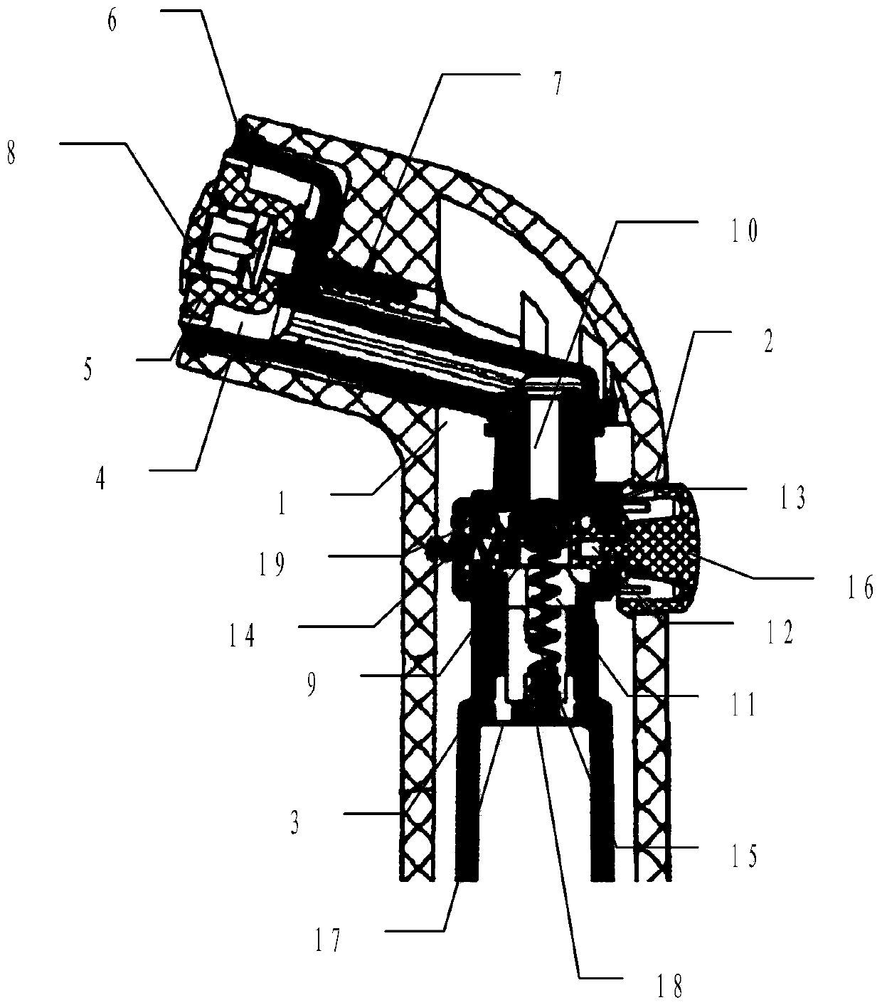
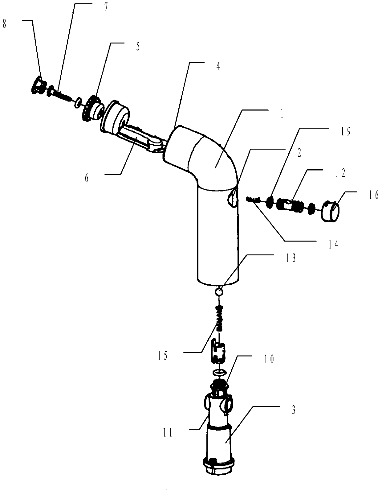
[0019] Such as figure 1 with figure 2 As shown, the present invention provides a water flow spray gun with a single-button micro-switch, including:

[0020] The spray gun body 1 is provided with a button opening 2 on its side wall, and an inner tube 3 is sleeved inside. The upper end of the inner tube is connected with the water outlet 4 of the spray gun body, and the spray gun front cover 5 is provided at the water outlet. The front cover is fixed at the water outlet by the fixed body 6, and the front cover of the spray gun is fixed with the fixed body by screws 7. An outer cover 8 is also installed outside the front cover of the spray gun. When the water flow spray gun is not in use, the outer cover is covered on the front cover of the spray gun. In order to prevent ...


PUM


Abstract

The invention relates to the field of bathroom accessories, particularly to a water spray gun with a micro-power single-button switch. The water spray gun with the micro-power single-button switch comprises a spray gun body, the side wall of the spray gun body is provided with a button through hole, an inner tube is embedded inside the spray gun body, the upper end of the inner tube is communicated with the water outlet of the spray gun body, a horizontal accommodating space which is communicated with the cavity of the inner tube is arranged in the middle of the inner tube, and the opening of the horizontal accommodating space is aligned to the button through hole; a water sealing column is arranged inside the horizontal accommodating space, one side of the water sealing column is connected to the inner wall of the inner tube through a horizontal elastic component, and the upper side and the bottom side of the water sealing column are provided with a vertical through hole; the sealing ball is arranged above the through hole, the lower end of a vertical elastic component is fixed to the inner tube, the upper end of the vertical elastic component is connected with the lower end of the sealing ball through the lower portion of the through hole, and the upper end of the sealing ball abuts against the inlet on the upper portion of the cavity of the inner tube under the action of the vertical elastic component; a button is embedded into the button through hole. The water spray gun with the micro-power single-button switch is laborsaving in button pressing and simple in structure.

Description

Technical field [0001] The invention relates to the field of sanitary ware, in particular to a water flow spray gun with a single-button micro-force switch. Background technique [0002] Traditional spray guns generally use large buttons, and use levers to open and close the water plug to realize the on and off of the water flow. The structure is complex, and the size and material performance of the buttons are high. The button and the lever ejection device cannot be completely fixed, the connection is unreliable, and the ejection force increases when the water pressure rises, which causes the pressure at the joint to increase, and the joint between the button and the water plug is very easy to wear, which brings trouble to the product. Determine the factors. The water pressure used by the spray gun is a normally closed static water pressure. When the working water pressure is too large, this single-sided pressure structure makes the operation of pressing the button laborious. ...

Claims


Application Information

Patent Timeline
IPC IPC(8): B05B12/00
CPCB05B12/002
Inventor 邱家森
Owner GUANGZHOU SEAGULL KITCHEN & BATH PROD
Why Eureka
Try Eureka