Rolling device

A technology for rolling punching and punching needles, applied in the field of rolling punching devices, can solve the problems of additional unloading equipment or manual unloading, damage to punching needles or die, and high labor costs, so as to save assembly costs and avoid punching needle damage. , the effect of reducing labor costs

Active Publication Date: 2016-06-08
XIAMEN ZHENGLIMING METALLURGICAL MACHINERY
View PDF5 Cites 0 Cited by
  • Summary
  • Abstract
  • Description
  • Claims
  • Application Information

AI Technical Summary

Problems solved by technology

It has the following disadvantages: 1. For each type of hole to be processed, a punching needle and a die are required. On the one hand, the cost is high; When punching, it is necessary to ensure that the punch needle and the die rotate synchronously. On the one hand, a transmission mechanism is required, such as a gear mechanism to connect the first roller unit and the second roller unit to ensure that the two rotate synchronously, which increases the cost. On the other hand, even if the matching The transmission mechanism may also have a slight difference in angular rotation, which will damage the punching needle or die; 3. When rolling punching, it is inconvenient to unload the material, and it needs to be equipped with unloading equipment or manual unloading; 4. Low precision

Method used


Image

  • Rolling device

Examples


Embodiment Construction

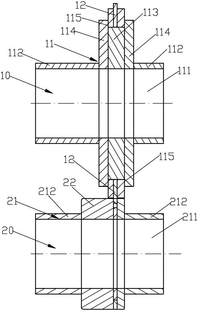
[0016] Please check figure 1 , a rolling device, including a frame, a rotatable first roller unit 10 arranged on the frame and a second roller unit 20 rotatably arranged on the frame. The axis of rotation of the first roller unit 10 is parallel to the axis of rotation of the second roller unit 20 . In this embodiment, the rolling device is more effective for rolling thin metal plates, such as thin plates with a thickness less than 0.5mm, and metals such as steel plates.

[0017] The first roller unit 10 includes a first rigid wheel 11 and at least one punching pin 12 disposed on the first rigid wheel 11 , of course, the tip of the punching pin 12 protrudes from the outer rotating surface of the first rigid wheel 11 . Preferably, the punching pins 12 are detachably fixed on the first rigid wheel 11, the number of the punching pins 12 is multiple, and the multiple punching pins 12 are evenly spaced in a ring. In this embodiment, the first rigid wheel 11 includes a first rotati...


PUM

PropertyMeasurementUnit
thicknessaaaaaaaaaa
thicknessaaaaaaaaaa
hardnessaaaaaaaaaa

Abstract

The invention discloses a roll punching device. The device comprises a rack and a first roller unit and a second roller unit which are arranged on the rack in a rotatable mode. The rotation axis of the first roller unit is parallel to the rotation axis of the second roller unit. The first roller unit comprises a first rigid wheel and at least one punching pin arranged on the first rigid wheel. The second roller unit comprises a second rigid wheel and a flexible layer surrounding the outer rotation surface of the second rigid wheel. A plate to be machined is arranged between the first roller unit and the second roller unit and can be subjected to roll punching through the matching of the punching needles and the flexible layer. The device has the advantages that female dies are omitted, the cost is reduced, exchanging of the female die is not needed, and accordingly, the labor cost is reduced; during roll punching, synchronous rotation of the punching pins and the female dies is not required, so that a matched synchronous mechanism is omitted, damage to the punching needles is prevented, and assembly costs are saved; during roll punching, unloading is convenient, roll punched waste can fall into an unloading tank as long as the unloading tank is arranged below the waste; the accuracy is high.

Description

technical field [0001] The invention relates to a rolling flushing device. Background technique [0002] The metal rolling device in the prior art includes a frame, a first roller unit that can rotate on the frame and a second roller unit that can rotate on the frame, the rotation axis of the first roller unit and The axes of rotation of the second roller unit are parallel. The first roller unit includes a first rigid wheel and at least one punch pin located on the first rigid wheel, the second roller unit includes a second rigid wheel and at least one die located on the second rigid wheel, the punch Needle and die fit. During processing, the board to be processed is placed between the first roller unit and the second roller unit, and the board to be processed is punched by the cooperation of the punching needle and the die. It has the following disadvantages: 1. For each type of hole to be processed, a punch needle and a die are required. On the one hand, the cost is hig...

Claims


Application Information

Patent Timeline
Patent Type & Authority Patents(China)
IPC IPC(8): B21D31/02
Inventor 黄溢忠陈辉煌程国宝张建强李斌
Owner XIAMEN ZHENGLIMING METALLURGICAL MACHINERY
Why Eureka
Try Eureka