Clamp for turning universal joint

A cross shaft and fixture technology, which is applied in the field of mechanical processing, can solve the problems of affecting the processing quality, troublesome and inaccurate clamping and correcting parts, etc.

Active Publication Date: 2014-04-23
ZOOMLION HEAVY IND CO LTD
View PDF7 Cites 25 Cited by
  • Summary
  • Abstract
  • Description
  • Claims
  • Application Information

AI Technical Summary

Problems solved by technology

Since the vertical axis is not clamped, the workpiece will bounce during processing, which will affect the processing quality
In addition, when the three-jaw chuck is clamped, it is difficult to ensure the coaxiality of the cylindrical shafts on both sides (that is, the two cylindrical shafts in the vertical direction). It is troublesome to clamp and correct parts, and the processing efficiency is not high.
Therefore, there are problems in the prior art that the cross-axis workpiece cannot be clamped and the positioning is inaccurate

Method used


Image

  • Clamp for turning universal joint
  • Clamp for turning universal joint

Examples


Embodiment Construction

[0026] Specific embodiments of the present invention will be described in detail below in conjunction with the accompanying drawings. It should be understood that the specific embodiments described here are only used to illustrate and explain the present invention, and are not intended to limit the present invention.

[0027] In the present invention, in the case of no contrary description, the used orientation words such as "up, down, left and right" usually refer to the up, down, left and right shown in the accompanying drawings; "inside and outside" Refers to the inside and outside of the outline of each part itself.

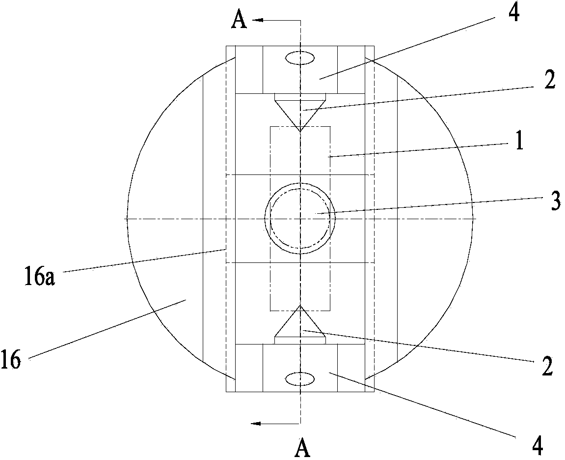
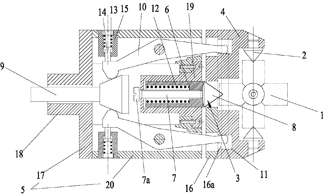
[0028] The present invention provides a jig for turning a cross shaft (hereinafter referred to as the jig), wherein the jig includes a first positioning mechanism for positioning the cross shaft workpiece 1 along the vertical axis direction of the cross shaft workpiece 1 and a A second positioning mechanism for positioning the cross-axis workpiece 1 along th...


PUM


Abstract

The invention discloses a clamp for turning a universal joint. The clamp comprises a first locating mechanism used for locating a universal joint work-piece (1) in the vertical shaft direction of the universal joint work-piece (1), and a second locating mechanism used for locating the universal joint work-piece (1) in the horizontal shaft direction of the universal joint work-piece (1). The first locating mechanism and the second locating mechanism can locate the universal joint work-piece in the vertical shaft direction and the horizontal shaft direction at the same time, and therefore the universal joint work-piece can be clamped in a centring mode, firm locating in the turning process is guaranteed, and the coaxiality of two cylindrical shafts on the two sides of a machined cylindrical shaft is guaranteed. The clamp can clamp and locate the universal joint work-piece accurately.

Description

technical field [0001] The invention relates to the field of mechanical processing, in particular to a fixture for turning a cross shaft. Background technique [0002] For the turning of the cross shaft, a typical part in the automobile differential, the conventional method is to use the three-jaw chuck that comes with the ordinary lathe. When the three-jaw chuck is used for clamping, only the front end cylinder of the cross-axis workpiece can be clamped. During initial processing, the tip of the tool is easily damaged by the vertical axis. Since the vertical axis is not clamped, the workpiece will bounce during processing, which will affect the processing quality. In addition, when the three-jaw chuck is clamped, it is difficult to ensure the coaxiality of the cylindrical shafts on both sides (that is, the two cylindrical shafts in the vertical direction). It is troublesome to clamp and correct parts, and the processing efficiency is not high. Therefore, there are problem...

Claims


Application Information

Patent Timeline
Patent Type & Authority Applications(China)
IPC IPC(8): B23Q3/00
CPCB23Q3/12
Inventor 金灿
Owner ZOOMLION HEAVY IND CO LTD
Why Eureka
Try Eureka