
A ultrasonic sensor fully automatic patch machine

A sensor and fully automatic technology, applied in the field of sensors, can solve the problems of low work efficiency, uneven strength, high defect rate, etc.

Active Publication Date: 2015-09-30
BESTAR HLDG +1
View PDF5 Cites 0 Cited by
  • Summary
  • Abstract
  • Description
  • Claims
  • Application Information

AI Technical Summary

Problems solved by technology

[0002] With the development of the electronics industry, the application of ultrasonic sensors is becoming more and more widespread. At this stage, the production of ultrasonic sensors mostly adopts manual or semi-automatic production methods, that is, manually apply glue in the shell, and then prevent the ceramic sheet from the shell In the body, the ceramic sheet is bonded to the shell by glue, which is very inefficient, and the bonding strength of the ceramic sheet to the shell is different, which also leads to poor performance consistency of the sensor and high defect rate. question

Method used


Image

  • A ultrasonic sensor fully automatic patch machine
  • A ultrasonic sensor fully automatic patch machine
  • A ultrasonic sensor fully automatic patch machine

Examples


Embodiment Construction

[0019] The present invention will be further described below in conjunction with the accompanying drawings and specific embodiments.

[0020] The drawings given in the embodiments show a schematic diagram of combining two full-automatic placement machines of a type of ultrasonic sensor, which can improve work efficiency.

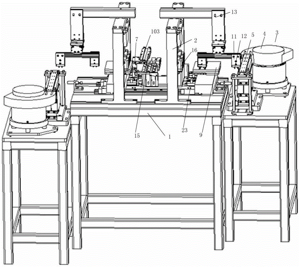
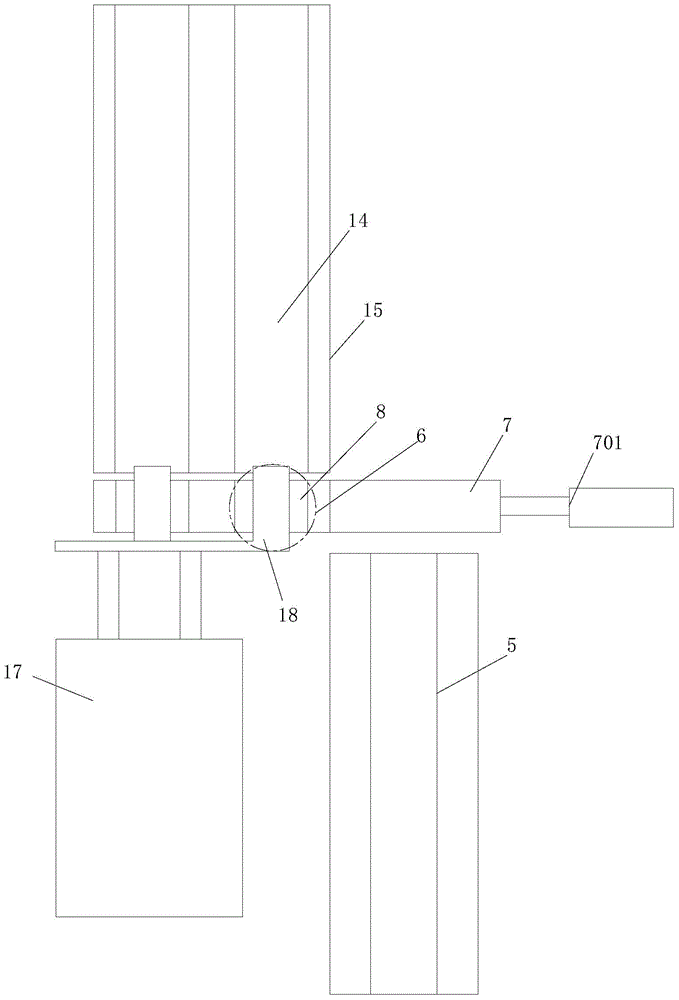
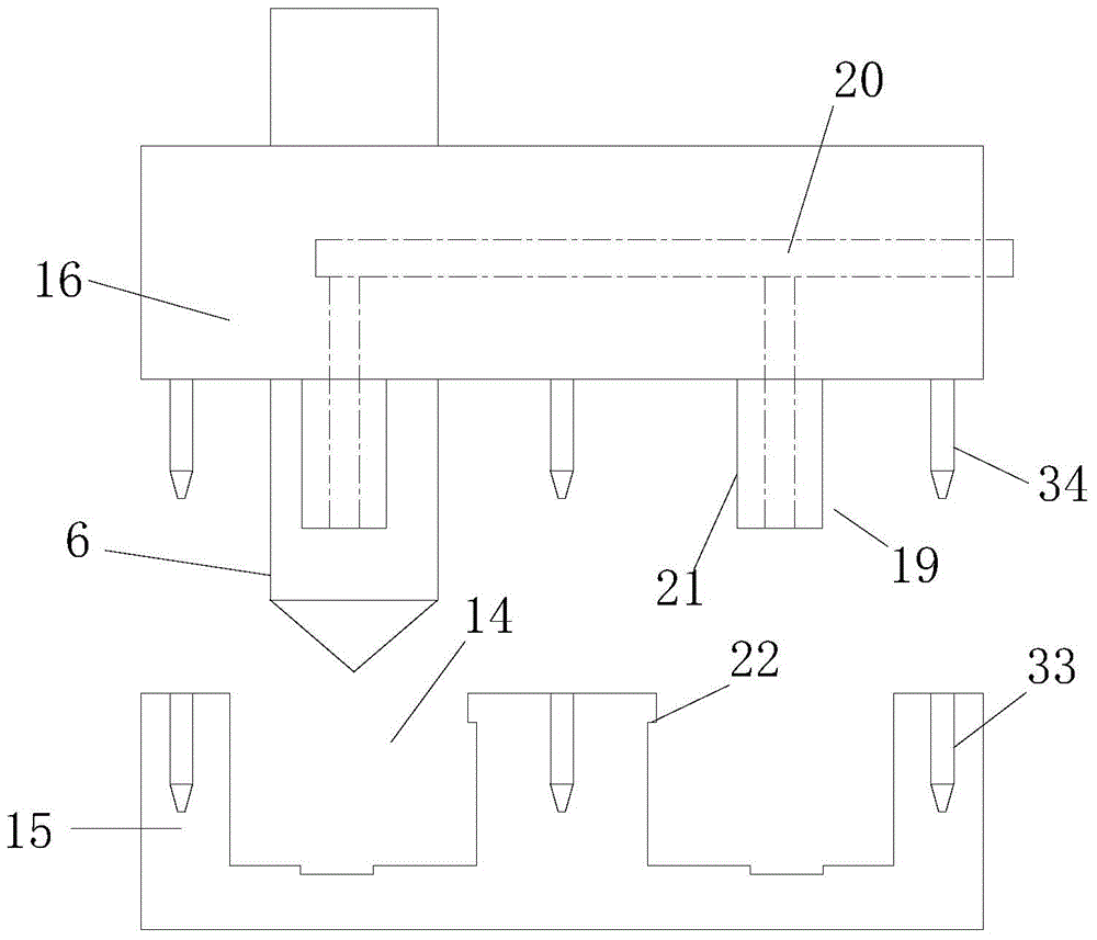
[0021] see Figure 1-5 , an ultrasonic sensor full-automatic placement machine, comprising a machine base 1, a bracket 2 is fixedly arranged on the machine base, a shell 101 vibration feeding mechanism, a tile 102 vibration feeding mechanism 3 are arranged on one side of the machine base, figure 1 The shell vibrating feeding mechanism is not shown in the figure, which is located at the rear of the entire device during specific assembly. The shell and ceramic chip vibrating feeding mechanisms are vibrating feeding equipment available on the market, including a vibrating plate 4 with an accommodating cavity. The spiral vibrating passage in the vibrating plate...


PUM


Abstract

The invention relates to a full-automatic surface mounting machine of an ultrasonic sensor. The full-automatic surface mounting machine comprises a housing, a ceramic chip vibration feeding mechanism, a dispensing machine, the feeding tail end and a mobile block; the housing is arranged on one side of a base; the dispensing machine is arranged on the base; the feeding tail end is located on a housing vibration feeding mechanism; the mobile block is arranged on the base and horizontally moves; the mobile block is provided with a limiting groove which is communicated with the feeding tail end of the housing vibration feeding mechanism; the base is provided with a bearing block; the tail end of the ceramic chip vibration feeding mechanism is provided with a rotating suction block; the base is provided with a limiting block and a pressing block; the limiting block comprises an accommodating channel and can horizontally move; the pressing block is located above the limiting block and can move up and down to be matched with the limiting block; one side of the mobile block is provided with a pushing mechanism which is used for pushing housings arranged in the limiting groove into the accommodating channel; the pressing block is provided with the adsorption end which is used for adsorbing and pressing ceramic chips located in the accommodating channel to the housings arranged in the accommodating housing. According to the full-automatic surface mounting machine of the ultrasonic sensor, vibration conveying is performed on the housings and the ceramic chips automatically, the housings and the ceramic chips are conveyed to the specified position, the ceramic chips are adsorbed to the housings through respective adsorption, and the pressure is maintained to enable the ceramic chips and the housings to be pressed together firmly.

Description

technical field [0001] The invention relates to the technical field of sensors, in particular to an ultrasonic sensor full-automatic placement machine. Background technique [0002] With the development of the electronics industry, the application of ultrasonic sensors is becoming more and more widespread. At this stage, the production of ultrasonic sensors mostly adopts manual or semi-automatic production methods, that is, manually apply glue in the shell, and then prevent the ceramic sheet from the shell In the body, the ceramic sheet is bonded to the shell by glue, which is very inefficient, and the bonding strength of the ceramic sheet to the shell is different, which also leads to poor performance consistency of the sensor and high defect rate. question. Contents of the invention [0003] In view of the above technical problems, the present invention provides a fully automatic placement machine for ultrasonic sensors, which can automatically paste ceramic chips and h...

Claims


Application Information

Patent Timeline
Patent Type & Authority Patents(China)
IPC IPC(8): F16B11/00
Inventor 龙阳邹东平李红元祁小柯马国阳余方云
Owner BESTAR HLDG
Learn More