Eureka AIR delivers breakthrough ideas for toughest innovation challenges, trusted by R&D personnel around the world.

High-precision dynamic flow balance valve

A dynamic flow, high-precision technology, applied in balance valves, sliding valves, safety valves, etc., can solve problems such as inconvenient inspection, maintenance, cleaning, affecting the stiffness of the valve core, and complex structures

Active Publication Date: 2014-04-23
ZHEJIANG DUNAN INTELLIGENT CONTROL TECH CO LTD +1
View PDF8 Cites 1 Cited by
  • Summary
  • Abstract
  • Description
  • Claims
  • Application Information

AI Technical Summary

Problems solved by technology

[0002] At present, a large number of dynamic flow balance valves of foreign imported brands are generally assembled in one piece. This high-precision automatic flow balance valve is not convenient for later inspection, maintenance, and cleaning. After long-term operation, the control accuracy will decrease and energy consumption will increase; while domestic The initial working pressure of the dynamic flow balance valve produced by the manufacturer is generally high, and the flow accuracy is low. The same problem exists in the later inspection, maintenance and cleaning, and the reliability is poor.
[0003] In the side opening method provided in Chinese patent CN 1888498A, the flow coefficient of the side flow hole used for calculation is a fixed value, and the flow coefficients of different positions of the side flow hole should be different, so high-precision flow control cannot be guaranteed
And when the required ideal flow rate is too large, the symmetrical and variable openings on both sides of the side flow channel are cut to the inner wall or even the outer wall of the valve core, which not only affects the stiffness of the valve core, but also cannot meet the flow demand
[0004] The return spring provided in the Chinese patent CN 201232764Y is used for positioning the valve cartridge, and the required valve body is relatively large and has a complicated structure
[0005] The side fixing hole provided in Chinese patent CN 2781125Y is a square hole, the rigidity is not high, and it is not conducive to increasing the flow rate
[0006] The side fixed holes provided in Chinese patent CN 2781128Y are multiple circular holes, and the side variable holes are multiple and unconnected, the processing is complicated, and it is not conducive to the one-time molding of wire cutting

Method used


Image

  • High-precision dynamic flow balance valve
  • High-precision dynamic flow balance valve
  • High-precision dynamic flow balance valve

Examples


Embodiment Construction

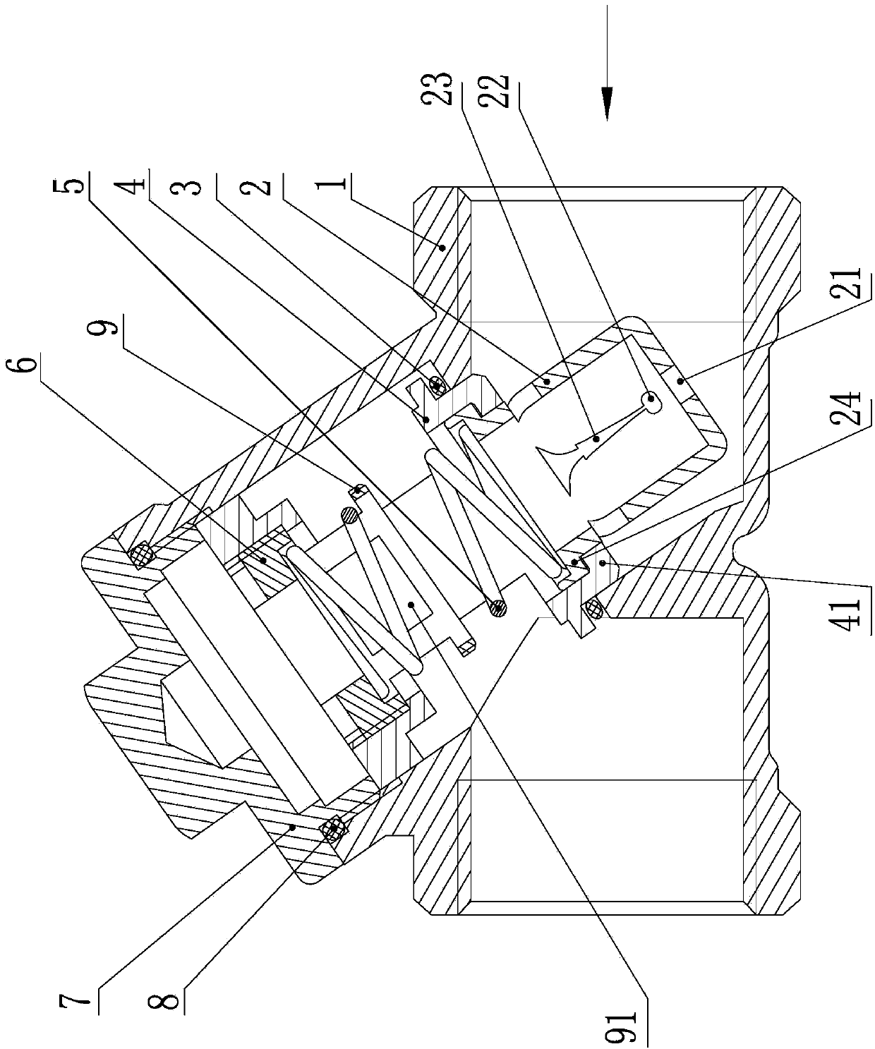
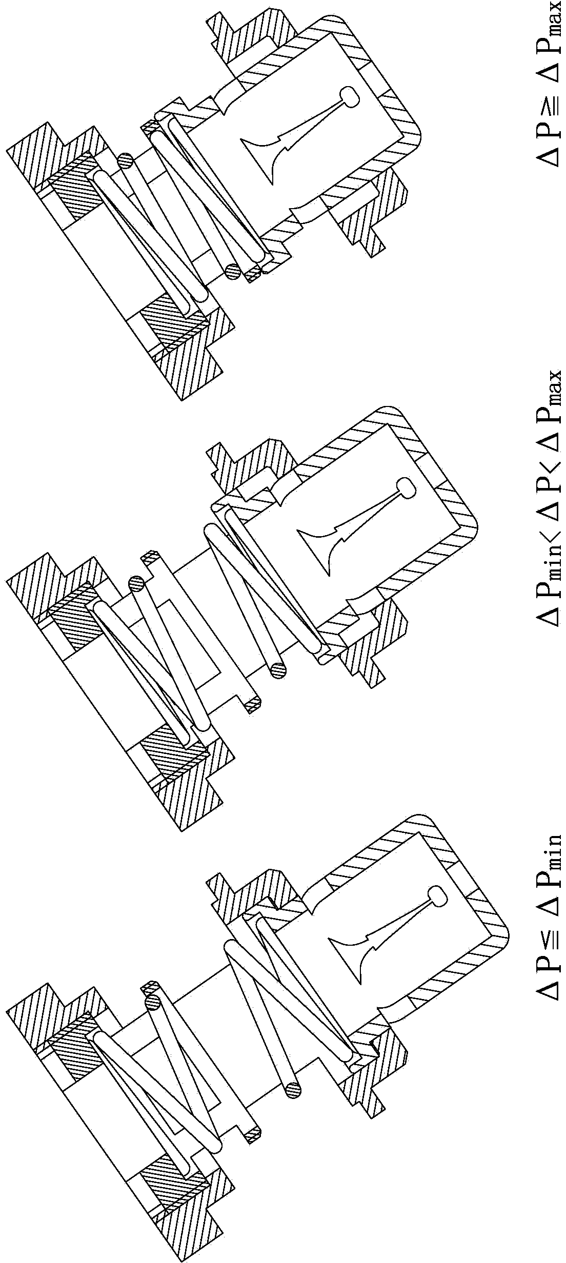
[0062] like figure 1 As shown, the high-precision dynamic flow balance valve of the present invention includes a valve core assembly and a valve cover 7 installed on the valve body 1. The valve core assembly is composed of a valve core 2, a valve core housing 4, a spring 5, and a locking screw 6. , the spool 2 is provided with a fixed hole 21 on the end surface and symmetrical side flow channels on both sides, the side flow channel includes two evenly distributed fixed elliptical holes 22, two or four evenly distributed variable holes 23, two fixed elliptical holes The holes 22 communicate with two symmetrically distributed variable holes 23 respectively.

[0063] In the case of small flow, the variable holes 23 in the present invention are set to two, and the two variable holes 23 are arranged symmetrically, and communicate with the corresponding fixed oval holes 22 one by one, while the two variable holes 23 The circulation area is the same.

[0064] In the case of a large...


PUM


Abstract

The invention relates to a flow control valve which is mainly applied to the field of air conditioner, heating and water supply systems where flow balancing is needed, in particular to a high-precision dynamic flow balance valve. The high-precision dynamic flow balance valve comprises a valve element component and a valve cover mounted on a valve body, the valve element component is composed of a valve element, a valve element shell, a spring and a locking screw, the valve element is provided with an end face fixing hole and side flow channels which are symmetrical on two sides, and each side flow channel comprises two evenly-distributed oval holes and two or four evenly-distributed variable holes, wherein the two fixed oval holes are communicated with two symmetric variable holes in a one-to-one mode. The high-precision dynamic flow balance valve is simple in structure, small in size, good in valve element rigidity, convenient to machine and capable of saving cost.

Description

technical field [0001] The invention relates to a flow control valve, which is mainly used in fields requiring balanced flow, such as air conditioning, heating, and water supply systems, and in particular relates to a high-precision dynamic flow balance valve. Background technique [0002] At present, a large number of dynamic flow balance valves of foreign imported brands are generally assembled in one piece. This high-precision automatic flow balance valve is not convenient for later inspection, maintenance, and cleaning. After long-term operation, the control accuracy will decrease and energy consumption will increase; while domestic The initial working pressure of the dynamic flow balance valve produced by the manufacturer is generally high, and the flow accuracy is low. The same problem exists in the later inspection, maintenance and cleaning, and the reliability is poor. [0003] In the side opening method provided in Chinese patent CN 1888498A, the flow coefficient of...

Claims


Application Information

Patent Timeline
IPC IPC(8): F16K17/04F16K3/26
CPCF16K3/26F16K3/34F16K17/046
Inventor 李树勋徐娟娟叶琛
Owner ZHEJIANG DUNAN INTELLIGENT CONTROL TECH CO LTD
Why Eureka
Eureka Blog
Learn More