Driving circuit of LED backlight and driving method thereof

A technology of backlight driving circuit and driving method, which is applied in the field of display screens to achieve the effects of increasing speed, improving correlation and reducing power output

Active Publication Date: 2014-04-23
SHENZHEN CHINA STAR OPTOELECTRONICS TECH CO LTD
View PDF6 Cites 4 Cited by
  • Summary
  • Abstract
  • Description
  • Claims
  • Application Information

AI Technical Summary

Problems solved by technology

At this time, the MCU has been added to the backlight driver for some data processing work, but in this way, the MCU can control the LED driver at most, so that the multi-channel LED current can be switched synchronously, but the power chip still works according to a fixed frequency. , In this way, the working frequency of DC-DC has no actual connection with the dimming frequency of multi-channels, so the real-time response of the power chip will be a test, and under low brightness, the power chip also works at a fixed frequency state, and the backlight drive circuit function Power consumption is still consistent with high brightness

Method used


Image

  • Driving circuit of LED backlight and driving method thereof
  • Driving circuit of LED backlight and driving method thereof
  • Driving circuit of LED backlight and driving method thereof

Examples


Embodiment Construction

[0032] The present invention will be further described below in conjunction with the accompanying drawings and preferred embodiments.

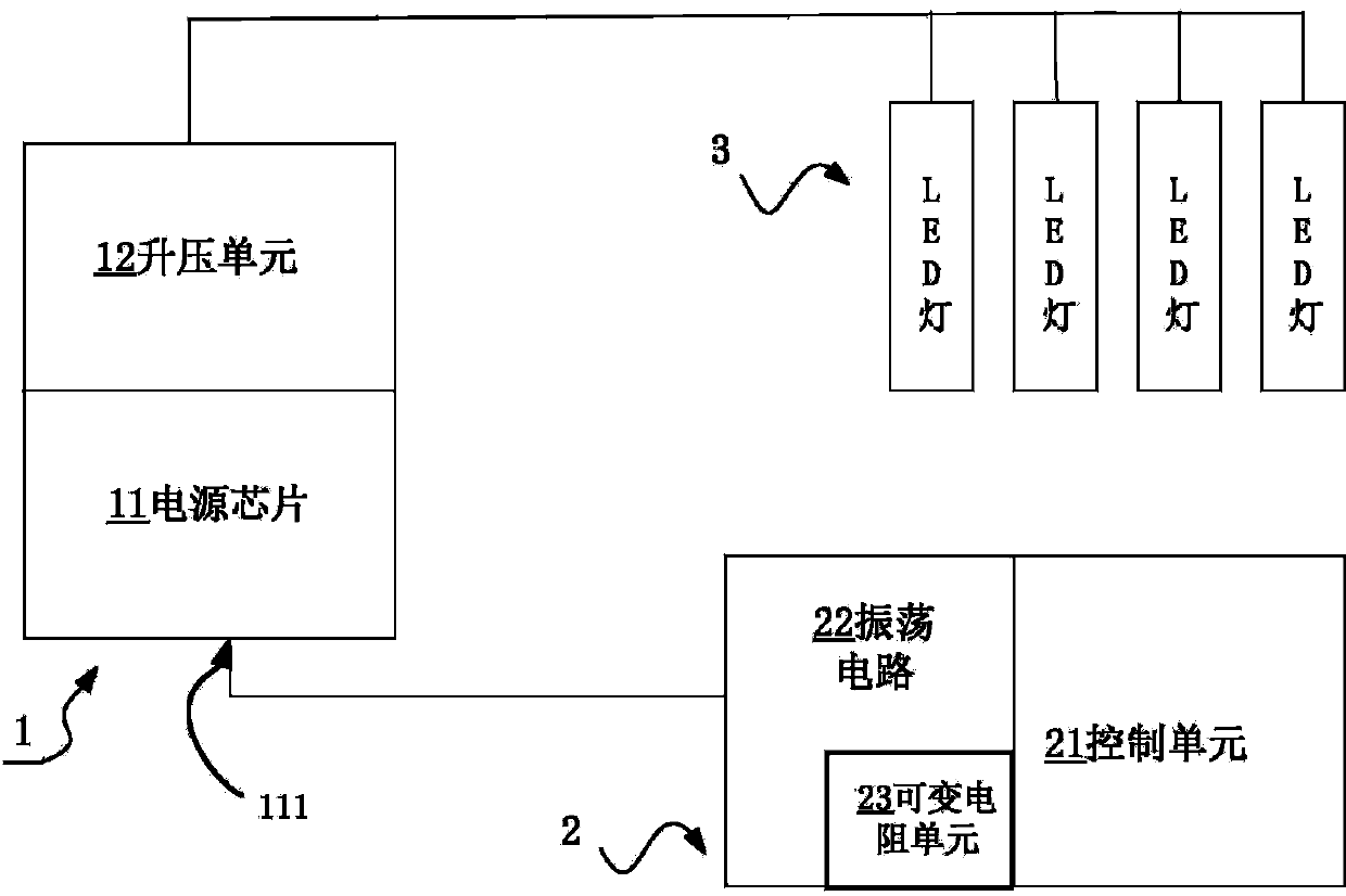
[0033] figure 1 It is a functional block diagram of a backlight drive circuit of the present invention, the drive circuit includes a power module 1, a control module 2 and at least two LED lamps 3, the control module 2 generates a power control signal according to the working state of the LED lamp 3, and the power module operates at power Under the control of the control signal, the output matches the power of the turned-on LED lamp.

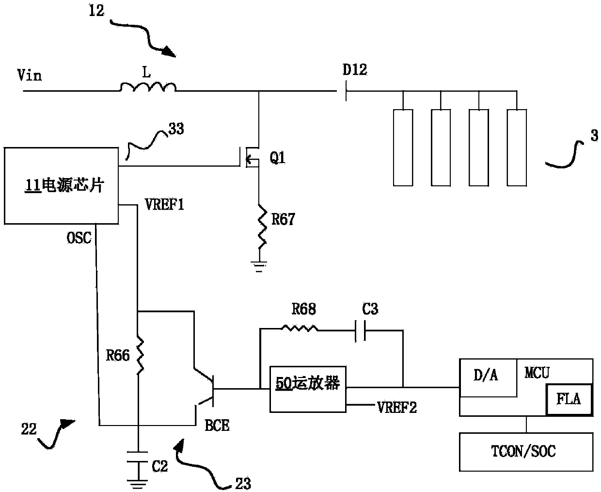
[0034] The above power module 1 includes a boost unit 12, a power chip 11, and the power chip 11 controls the output power of the boost unit 12 through frequency; the power chip 11 includes a frequency control pin 111; The control module 2 includes an oscillating circuit 22 and a control unit 21, the oscillating circuit 22 includes a variable resistance unit 23; the control unit 2 generates a resistance control...


PUM


Abstract

The invention discloses a driving circuit of LED backlight and a driving method thereof. The driving circuit includes a power module, a control module and at least two LED lamps. The control module based on the LED light working state generates a power control signal. The power module based on the power control signal outputs a power matched with the turned-on LED light. The driving circuit of the LED backlight can reduce the power consumption.

Description

technical field [0001] The present invention relates to the field of display screens, more specifically, to a driving circuit and a driving method for a backlight unit of a display screen. Background technique [0002] Now the backlight drive of the display screen is no longer simply lighting up the LED. Some backlights have multiple adjustment methods, such as LOCAL DIMMING, 3D SANNING, etc. At this time, the MCU has been added to the backlight driver for some data processing work, but in this way, the MCU can control the LED driver at most, so that the multi-channel LED current can be switched synchronously, but the power chip still works according to a fixed frequency. , In this way, the working frequency of DC-DC has no actual connection with the dimming frequency of multi-channels, so the real-time response of the power chip will be a test, and under low brightness, the power chip also works at a fixed frequency state, and the backlight drive circuit function Power con...

Claims


Application Information

Patent Timeline
Patent Type & Authority Applications(China)
IPC IPC(8): G09G3/34H05B44/00
CPCG09G3/3406G09G2320/062G09G2330/021H05B47/10H05B45/38H05B45/10
Inventor 杨翔
Owner SHENZHEN CHINA STAR OPTOELECTRONICS TECH CO LTD
Why Eureka
Try Eureka