
A Calibration Circuit for Eliminating Capacitance Mismatch Error

A capacitance mismatch and calibration circuit technology, applied in the field of calibration circuits, can solve the problems of inability to compensate for mismatch errors, increase calibration DACs, increase circuit costs, etc., and achieve the effects of improving accuracy, maintaining symmetry, and saving layout area.

Inactive Publication Date: 2017-02-01
BEIJING MXTRONICS CORP +1
View PDF4 Cites 0 Cited by
  • Summary
  • Abstract
  • Description
  • Claims
  • Application Information

AI Technical Summary

Problems solved by technology

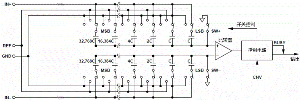
[0004] The above traditional method of storing errors and then compensating for capacitance mismatch has the following problems: 1. Taking the differential input SAR structure ADC as an example, the traditional error calibration DAC compensates the capacitance at one end of the differential capacitance pair, so it is usually placed in One side of the compensated capacitor array
This method can more accurately realize the compensation of the capacitance mismatch error, but the disadvantage is that the added calibration DAC will occupy a larger area
However, it is accompanied by a substantial increase in the layout area, which greatly increases the cost of the circuit.
On the other hand, the range of error compensation that can be achieved for each capacitor is limited, and large mismatch errors cannot be compensated

Method used


Image

  • A Calibration Circuit for Eliminating Capacitance Mismatch Error
  • A Calibration Circuit for Eliminating Capacitance Mismatch Error
  • A Calibration Circuit for Eliminating Capacitance Mismatch Error

Examples


Embodiment Construction

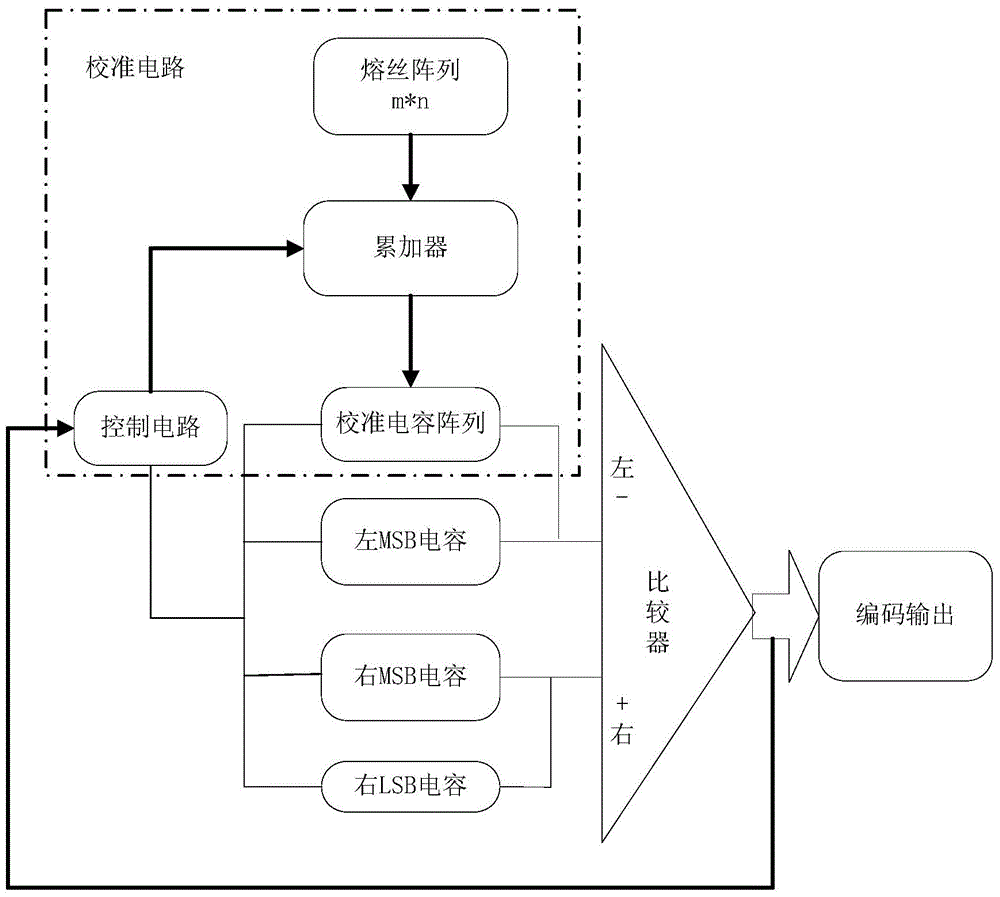
[0024] The calibration circuit of the present invention that adopts the fuse trimming technology to eliminate the capacitance mismatch error includes a fuse array, an accumulator, a control circuit and a calibration capacitor array.

[0025] The fuse array is composed of m times n fuses, m is the number of rows of the fuse array, n is the number of columns of the fuse array, where x acts as a data fuse, m, n, and x are all natural numbers, and x is less than m , The values ​​of m and n and the proportion of data fuses in the fuse array should be determined according to the needs of specific circuits. The mismatch error data that needs to be adjusted is stored in the data fuse; the accumulated result of each row of data fuse represents the error information that needs to be compensated, and the data of each row of data fuse is read out in its corresponding clock cycle and sent to The input of the accumulator is compensated.

[0026] When debugging the circuit, you can adjust t...


PUM


Abstract

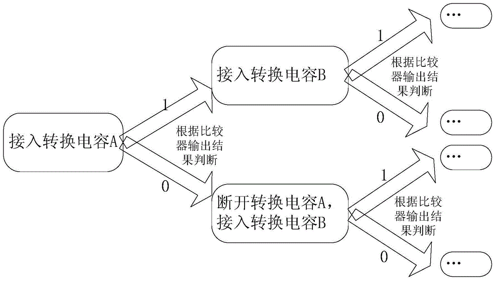
The invention provides a calibration circuit eliminating a capacitor mismatch error. The calibration circuit comprises a fuse array, an accumulator, a control circuit and a calibration capacitor array. Data fuses in the fuse array store mismatch error data. The calibration capacitor array is a left LSB capacitor array in a differential capacitor array. The accumulator reads data fuse values in turn. Connection or disconnecton of capacitors in the calibration capacitor array is controlled under the effect of the control circuit according to output results of a comparator so that capacitor calibration and conversion are completed. The calibration capacitor array and the left LSB capacitor array are combined as one so that layout area is greatly saved. Error information of each high-order capacitor is expressed by using one row of data fuses, and the error information of multiple low-order capacitors is expressed by using one row of data fuses so that contradiction of compensation precision and fuse array scale is compromised. With application of the calibration method, precision of a successively approximate type analog-to-digital converter is enhanced from a conventional 12bit to 16bit and even 18bit.

Description

technical field [0001] The invention relates to a calibration circuit, in particular to a calibration circuit which adopts a fuse trimming technique to eliminate capacitance mismatch errors, and is applied to a differential input successive approximation analog-to-digital converter. Background technique [0002] With the rapid development of portable mobile devices, low-power analog-to-digital converters are increasingly favored by electronic engineers. Successive approximation analog-to-digital converters (SAR structure ADCs) have become mainstream in low-power applications due to their inherent advantages. Limited by the process conditions of the foundry, the minimum mismatch rate of capacitors is 0.1%, so the accuracy of the successive approximation analog-to-digital converter can only reach 12 bits, which cannot meet the requirements of some high-precision applications. The use of laser trimming technology can eliminate the mismatch error of the capacitor, thereby impro...

Claims


Application Information

Patent Timeline
Patent Type & Authority Patents(China)
IPC IPC(8): H03M1/06
Inventor 李浩王宗民张铁良杨松虞坚
Owner BEIJING MXTRONICS CORP
Learn More