Microphone and its assembly method

A microphone and insulating cavity technology, applied in the field of sound and electricity, can solve the problems of large internal space of the microphone, small acoustic cavity behind the microphone, complicated assembly process, etc., and achieve the effect of simple assembly process, simplification of assembly process, and reduction of assembly links.

Active Publication Date: 2017-06-20
GOERTEK MICROELECTRONICS CO LTD
View PDF4 Cites 0 Cited by
  • Summary
  • Abstract
  • Description
  • Claims
  • Application Information

AI Technical Summary

Problems solved by technology

[0004] 1. The assembly process is complicated and the cost is high;
[0005] 2. The internal space of the microphone occupied by the cavity is relatively large, resulting in a small rear cavity of the microphone and low sensitivity

Method used


Image

  • Microphone and its assembly method
  • Microphone and its assembly method
  • Microphone and its assembly method

Examples


Embodiment 1

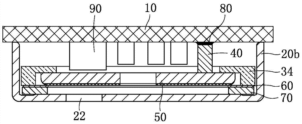
[0031] Such as figure 2 As shown, a microphone includes a circuit board 10 and a shell 20b with one end open, and the open end of the shell 20b is combined with the circuit board 10 and packaged as one. Define that the side of the circuit board 10 inside the package is called the inside, and the side outside the package is called the outside; the side of the shell 20b inside the package is called the inside, and the side outside the package is called the outside. The inner side of the circuit board 10 is provided with a number of electronic components 90, and the inner side of the casing 20b is provided with a diaphragm 70, a gasket 60 and a pole plate 50 in sequence, and the pole plate 50 is electrically connected with the circuit board 10 through a conductive post 40, and the conductive post 40 It is fixed and electrically connected with the circuit board 10 by conductive glue 80, and the conductive glue can absorb the tolerance formed during the processing of each componen...

Embodiment 2

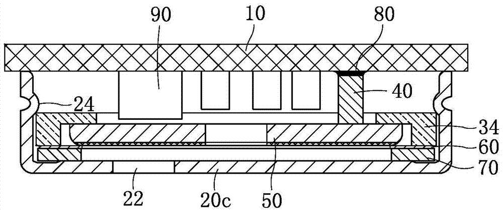
[0041] Such as image 3 As shown, this embodiment is basically the same as Embodiment 1, the difference is:

[0042] At least two bosses 24 are provided on the inner side wall of the housing 20c, and each boss 24 is distributed at the same height of the side wall of the housing 20c at equal intervals. Each boss 24 is arranged on the edge of the insulating cavity 34 close to the circuit board 10, and is used to constrain the insulating cavity 34 to prevent it from being biased or moving toward the direction of the circuit board 10, thereby ensuring that the position of the pole plate 50 is stable. This implementation In this way, even if the insulating cavity 34 is not fixedly connected with the spacer 60 , the pole plate 50 will not be dislocated.

[0043] The preferred solution is to have four bosses 24, one on each side wall of the casing 20c, so that the position of the insulating cavity 34 can be more effectively guaranteed to be stable without bias or misalignment, there...


PUM


Abstract

The invention discloses a microphone and an assembly method thereof, relating to the field of electro-acoustic technology, comprising a circuit board and a casing packaged as one, and a diaphragm, a gasket and The pole plate, the diaphragm is close to the bottom of the shell, and the pole plate is electrically connected to the circuit board through a conductive column; an annular insulating cavity is also provided, and the insulating cavity is arranged around the Around the pole plate, one end of the insulating cavity is connected to the gasket, and the other end of the insulating cavity is provided with a boss portion extending toward the center of the insulating cavity, and the boss portion is located on the Between the pole plate and the circuit board is used to constrain the pole plate. The microphone and its assembly method of the invention solve the technical problems of complicated microphone assembly process and low sensitivity in the prior art. The assembling procedure of the microphone of the invention is simple and convenient, and the cost is low and the sensitivity is high.

Description

technical field [0001] The invention relates to the field of acoustic and electric technologies, in particular to a microphone and an assembly method thereof. Background technique [0002] A microphone is an energy converter that converts sound signals into electrical signals. With the rapid development of electronic technology in recent years, microphones have also been widely used in portable electronic devices. [0003] Such as figure 1 As shown, the microphone in the prior art includes a packaged circuit board 10 and a housing 20a, and the space enclosed by the circuit board 10 and the housing 20a accommodates a diaphragm 70, a gasket 60, a pole plate 50 and a circuit board arranged on the circuit board. The electronic component 90 on 10, the pole plate 50 and the circuit board 10 are electrically connected through the conductive column 40, and the first cavity 30 is surrounded between the pole plate 50 and the shell 20a, and the first cavity 30 is used for the pole pla...

Claims


Application Information

Patent Timeline
Patent Type & Authority Patents(China)
IPC IPC(8): H04R19/04H04R31/00
Inventor 王友周天铎林伟李忠凯
Owner GOERTEK MICROELECTRONICS CO LTD
Why Eureka
Try Eureka