Orthodontic self-ligating bracket

A self-locking bracket and orthodontic technology, applied in the field of orthodontics, can solve the problems of difficult manufacturing, difficult operation, complicated structure, etc., and achieve the effect of simple production, no tedious operation and good effect.

Active Publication Date: 2014-04-30
ZHEJIANG SHINYE MEDICAL TECH CORP LTD
View PDF6 Cites 4 Cited by
  • Summary
  • Abstract
  • Description
  • Claims
  • Application Information

AI Technical Summary

Problems solved by technology

At present, there are many kinds of self-locking brackets on the market, including two series of active type and passive type, but the structure is relatively complicated, the manufacture is difficult, the cost is high, the price is expensive, and the operation is difficult.

Method used


Image

  • Orthodontic self-ligating bracket
  • Orthodontic self-ligating bracket
  • Orthodontic self-ligating bracket

Examples


Embodiment 1

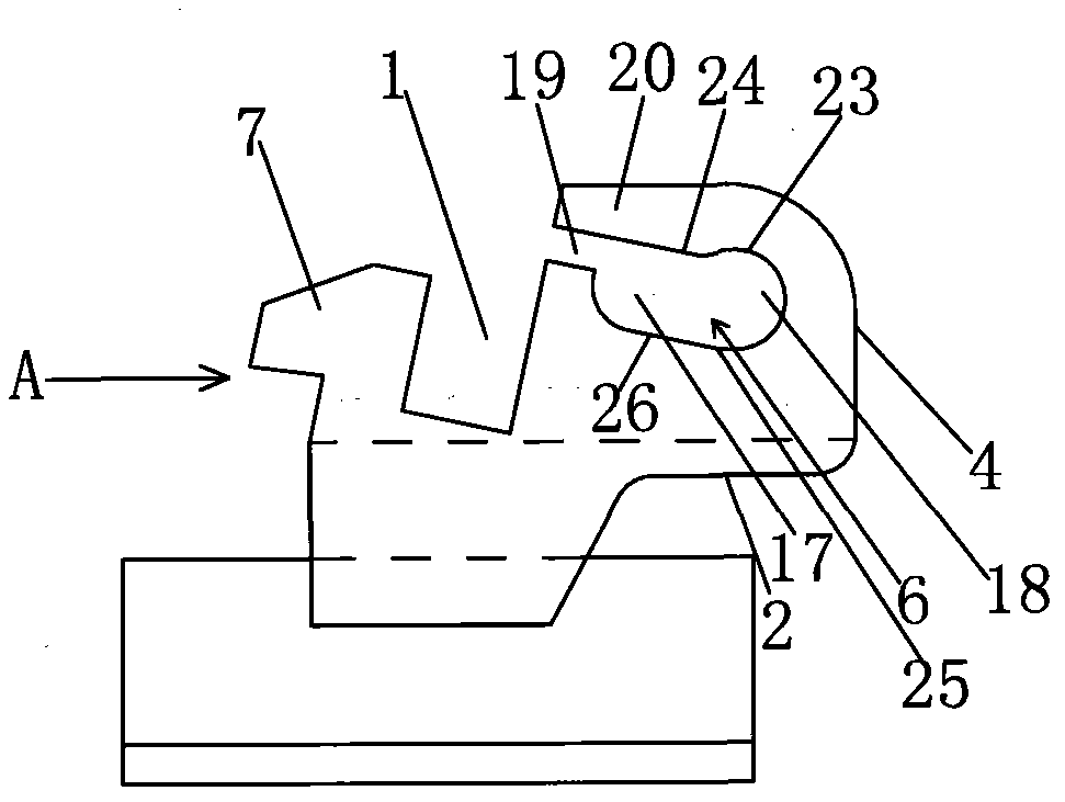
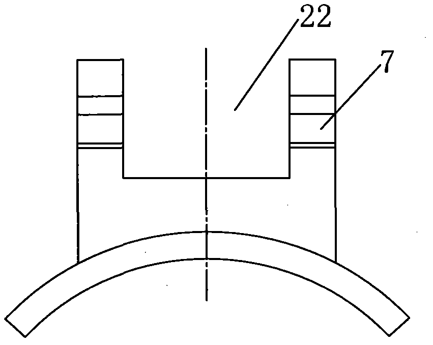
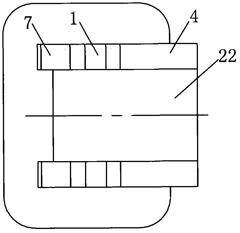
[0034] Embodiment 1: A self-ligating bracket for orthodontics, such as Figure 1~3 As shown, it includes a bracket body 2 with an archwire groove 1 and a bracket cover 8 matched with the bracket body 2. The right side of the archwire groove 1 is provided with a working wing 4. The intersecting thread groove groove 1 is provided with bracket opening 22; Figure 4~6 As shown, the bracket cover 8 is T-shaped as a whole, and the bracket cover 8 includes a wide portion 9 and a narrow portion 10. A shaft hole 12 formed by wire cutting is provided on the flange 11 on the bottom surface of the narrow portion 10 of the bracket cover. The narrow portion 10 of the bracket cover is disposed in the bracket opening 22, and a pin shaft 13 is pierced in the shaft hole 12 of the narrow portion 10 of the bracket cover, and the pin shaft 13 is cylindrical.

[0035] On the working wing 4 on the right side of the arch wire groove 1, there is a kidney hole 6 formed by wire cutting. The kidney hole...

Embodiment 2

[0042] Embodiment 2: As a deformation to the bracket body, such as Figure 9 As shown, a protrusion 27 is provided in the middle of the upper end surface of the waist hole 6 to limit the pin shaft. The protrusion 27 is an arc-shaped protrusion. Similarly, the protrusion can also be arranged under the waist hole. In the middle of the end face, there is an opening 19 formed by wire cutting on the working wing 4 on the right side of the archwire groove 1. The two sides of the opening 19 communicate with the archwire groove 1 and the kidney hole 6 respectively. The kidney hole 6 and the opening The part of the working wing above 19 forms a shrapnel 20 that can be deformed under force; in the locked state, the pin shaft is on the right side of the waist hole; when the bracket cover is opened, the pin shaft moves to the left and jumps over the protrusion 27 to force the shrapnel to generate Deform to enter the left side of the kidney hole.

Embodiment 3

[0043] Embodiment 3: As another deformation of the bracket body, such as Figure 10 As shown, in the direction perpendicular to the arch wire groove 1, the kidney hole 6 is divided into two sections, the left half section is a straight hole 17 with both upper and lower ends being straight lines, and the right half section is an arc-shaped hole 18. The bottom of the arc hole 18 is lower than the lower end face of the straight hole 17, the top of the arc hole is flush with the upper end face of the straight hole, and an L-shaped through hole 16 is cut down along the left end of the waist hole 6 to the right. The part surrounded by the L-shaped through hole 16 and the kidney hole 6 forms an elastic piece 20 that can be deformed under force; when in the locked state, the pin shaft is in the arc-shaped hole 18 on the right side of the kidney hole; when the bracket cover is opened, the pin The shaft leaves the arc hole to force the deformation of the shrapnel 20 and enters into the ...


PUM


Abstract

The invention discloses an orthodontic self-ligating bracket which comprises a bracket body and a bracket cover, wherein a bracket hole is formed in the bracket body in a manner of being crossed with an arch wire colpus; the bracket cover is T-shaped on the whole and comprises a wide part and a narrow part; a shaft hole is formed in the bracket cover; the narrow part of the bracket cover is arranged in the bracket hole; a pin shaft is arranged in the shaft hole of the narrow part of the bracket cover in a penetration manner; a kidney-shaped hole which is formed by wire cutting and used for clamping and positioning the pin shaft is formed in a working wing on the right side of the arch wire colpus; the pin shaft is arranged in the kidney-shaped hole in a penetration manner; a boss horizontally extends on the bracket body on the left side of the arch wire colpus in a direction deviating from the arch wire colpus; a bent hook is arranged at the wide part of the bracket cover; the wide part of the bracket cover is used for covering the boss on the left side of the arch wire colpus; the bent hook is matched with the boss; the pin shaft can be in different positions of the kidney-shaped hole along with the front-rear motion of the bracket cover, and the boss can be clamped in or separated from the bent hook along with the motion of the bracket cover, so that the bracket cover can be in a closed or opened state.

Description

technical field [0001] The invention relates to the technical field of orthodontics, in particular to a self-locking bracket for orthodontics. Background technique [0002] At present, in the process of orthodontic treatment of oral teeth, the orthodontic bracket is fixed on the tooth surface, and the arch wire passes through the arch wire slot (also known as the square wire slot) on the bracket, and is bound by a rubber ring or a steel wire. The arch wire is directly ligated in the arch wire groove of the bracket, and the correction force of the arch wire is transmitted to the teeth through the bracket, so that the teeth will move as expected, so as to achieve the purpose of correcting the teeth. [0003] Since the currently used ligation rubber ring or ligation steel wire is ligated on the ligation wing of the bracket, it directly exerts force on the arch wire, which produces a large pressure on the arch wire, hinders the normal movement of the arch wire, and thus affects ...

Claims


Application Information

Patent Timeline
Patent Type & Authority Applications(China)
IPC IPC(8): A61C7/34
Inventor 王光良
Owner ZHEJIANG SHINYE MEDICAL TECH CORP LTD
Why Eureka
Try Eureka