
Spanner

A wrench and trigger technology, applied in the field of wrenches, can solve the problems of easy deformation of the spring leaf, inconvenient normal use, large application, etc., and achieve the effects of preventing random rotation, reducing operation difficulty, and avoiding force damage

Inactive Publication Date: 2014-04-30
NINGBO BLACKPINE TOOLS CO LTD
View PDF9 Cites 2 Cited by
  • Summary
  • Abstract
  • Description
  • Claims
  • Application Information

AI Technical Summary

Problems solved by technology

However, this kind of wrench, after the wrench clamps the operation object, is locked by pressing the spring leaf through the deformation of the pressing rod. In order to make the handle retract and push the pressing rod and the deformation of the spring leaf, a large grip force needs to be applied. Before the jaws are adjusted to an appropriate size (that is, before locking), the handle must be kept firmly, which increases the difficulty of operation. In addition, the spring leaf is easily deformed after long-term use, resulting in the accumulation of the number of times of use. The force is getting bigger and bigger, which brings inconvenience to normal use

Method used


Image

  • Spanner
  • Spanner
  • Spanner

Examples


Embodiment Construction

[0021] The present invention will be further described in detail below in conjunction with the accompanying drawings and embodiments.

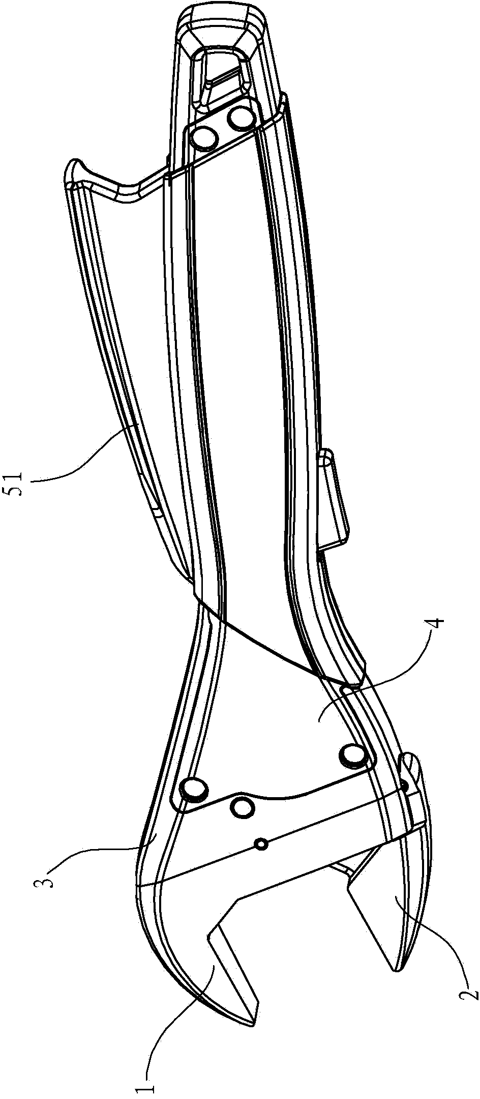
[0022] see figure 1 , a wrench, comprising an upper jaw 1 and a lower jaw 2, the lower jaw 2 is driven by a feed mechanism to move in the direction of the upper jaw 1, and the lower jaw 2 is driven by a reset mechanism to return to an initial position, the feed mechanism and the reset The mechanism is housed within the wrench housing formed by housing 3 and housing cover 4 .

[0023] For the convenience of description, hereinafter, the terms "front end (front)" and "rear end (rear)" are used, "front end (front)" refers to the end close to the object to be operated, and "rear end (rear)" Refers to the end away from the operand.

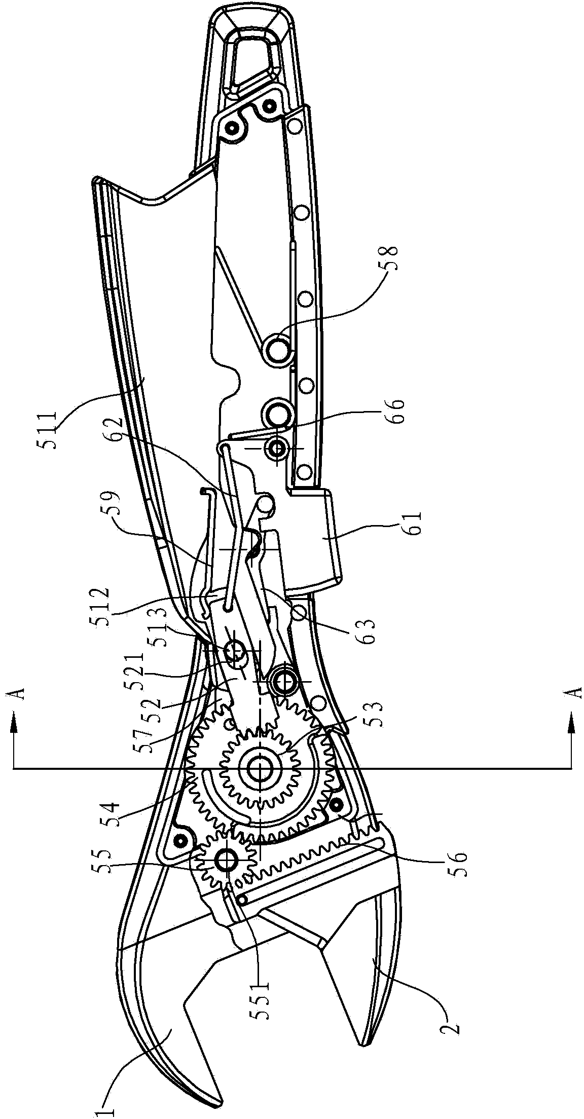
[0024] see figure 2 with Figure 5 , the feed mechanism includes a feed trigger 51, the feed trigger 51 includes a pressing portion 511 extending out of the wrench housing, the front end of the feed trigger 51 loc...


PUM


Abstract

The invention discloses a spanner which comprises an upper spanner opening, a movable lower spanner opening and a spanner shell. The lower spanner opening is driven by a feeding mechanism to act to move linearly opposite to the upper spanner opening, the feeding mechanism comprises swinging teeth, a driven gear meshed with the front ends, of saw teeth of the swinging teeth, and a feeding gear coaxial with the driven gear and driving the lower spanner opening, and the feeding gear is meshed with a brake ratchet ensuring that the feeding gear rotates in one direction. The spanner is characterized in that a one-way bearing is fixedly arranged in the driven gear, the feeding mechanism further comprises a feeding trigger connected with the spanner shell in a rotating mode, the feeding trigger is provided with a pressing portion extending out of the spanner shell, and the swinging teeth and the feeding trigger are located on the front end portion in the spanner shell and rotate synchronously; the spanner further comprises a reset mechanism which comprises a reset trigger which drives the swinging teeth to be separated from the driven gear and enables the brake ratchet to be separated from the feeding gear.

Description

technical field [0001] The invention relates to a hand fastening tool, especially a wrench. Background technique [0002] A wrench is a fastening tool commonly used for maintenance in daily life, especially an adjustable wrench. A common adjustable wrench consists of a handle, a fixed foot and a movable foot, wherein the handle and the fixed foot are fixed as a whole, and the movable foot moves in a straight line through the structure of the worm gear, thereby making the width between the fixed foot and the movable foot adjustable. It can be applied to operating objects of different specifications, such as hexagonal head screws or bolts, and is used in occasions where the operating objects are uncertain and you don't want to bring too many tools. [0003] However, in the actual use process, it is usually encountered that one hand needs to assist in supporting parts, the body, etc., and the other hand can only operate the wrench with one hand, resulting in inconvenient opera...

Claims


Application Information

Patent Timeline
IPC IPC(8): B25B13/56
CPCB25B13/14B25B13/22
Inventor 黄跃
Owner NINGBO BLACKPINE TOOLS CO LTD
Learn More