Sludge drying machine

A sludge drying and drying technology, which is applied in the direction of dehydration/drying/concentrated sludge treatment, etc., can solve the problems of high water content of sludge on the sludge inlet side, rail gnawing, and low resistance.

Active Publication Date: 2014-04-30
张伯涵
View PDF4 Cites 4 Cited by
  • Summary
  • Abstract
  • Description
  • Claims
  • Application Information

AI Technical Summary

Problems solved by technology

[0002] In the prior art, the technical solution closest to this application is a kind of sludge turning and drying machine in use. The structure of this drying machine is that there are longitudinal driving on two vertical vertical walls, A horizontal turning and throwing machine is installed below, and there is a drying bed between the two vertical vertical walls. The drying bed adopts a ceramsite layer and a gravel layer. , because on the drying bed, the sludge on the inlet side has a high moisture content and high resistance, while the sludge on the outlet side has a low moisture content and low resistance, which makes the force on both sides of the turner unbalanced, resulting in inconsistent walking resistance on both sides of the vehicle. Then there is the phenomenon of "driving rail gnawing"; second, the thickness of the sludge turning and throwing cannot exceed the horizontal axis of the turning and throwing machine, so the thickness of the sludge is limited; third, when working, the turning and throwing machine needs to be on the bottom The sludge is turned over at the same time, so the turning machine needs a lot of power; moreover, using a drying bed composed of ceramsite layers to carry sludge cannot prevent sludge particles from gradually clogging the gaps between ceramsites, and will eventually Affect the ventilation effect, these defects are the deficiencies in the existing technology

Method used


Image

  • Sludge drying machine

Examples


Embodiment Construction

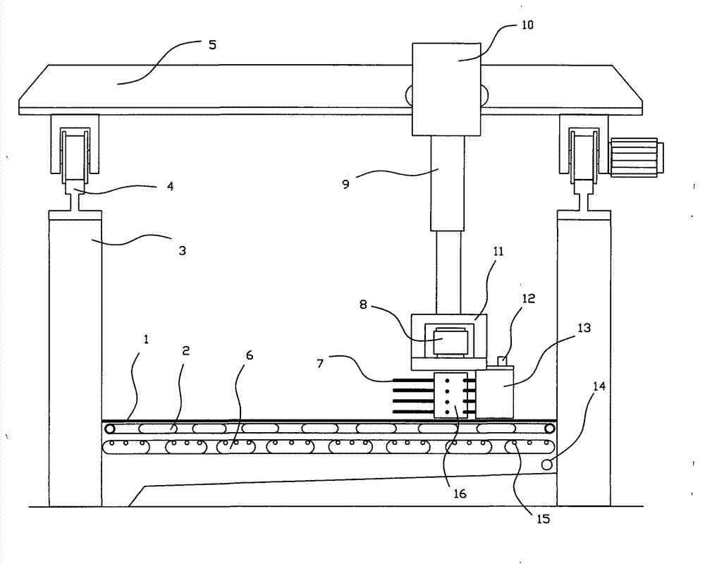
[0008] In order to clearly illustrate the technical features of the solution, the solution will be described below through a specific implementation mode combined with the accompanying drawings.

[0009] It can be seen from the accompanying drawings that the sludge drying machine of this program has two vertical vertical walls 3, a drying bed is arranged between the two vertical walls 3, and a vertical guide rail 4 is respectively arranged on the upper top surface of the two vertical walls 3 , on two vertical guide rails 4, longitudinal driving 5 is housed, and the drying bed described in this program is that the top surface is made of the bed board 1 that is densely covered with through holes and the heating pipe 2 and the ventilation pipe 6 under the bed board 1. The bed board 1 described in the specific implementation mode of this program adopts a steel plate with densely distributed tiny through holes. The heating pipe 2 described in the specific implementation mode of thi...


PUM


Abstract

The invention provides a device for processing sludge in sewage treatment, and in particular provides a technical solution of a sludge drying machine. The solution comprises two vertical walls, wherein a drying bed is arranged between the two vertical walls; a vertical guide rail is arranged on the top surface of each vertical wall, and a vertical crane is arranged on the two vertical guide rails, wherein the drying bed is composed of a bed board which is densely distributed with small through holes on the top surface as well as a heating pipe and a vent pipe below the bed board; a transverse crane is arranged on the vertical crane; a sludge sweeper is hung below the transverse crane through a telescopic hanging rod; the sludge sweeper is composed of sludge sweeping rollers which are driven by a sludge sweeping motor and are provided with a sludge sweeping brush.

Description

technical field [0001] The invention relates to a sludge treatment device for sludge obtained in sewage treatment, in particular to a sludge dryer. Background technique [0002] In the prior art, the technical solution closest to this application is a kind of sludge turning and drying machine in use. The structure of this drying machine is that there are longitudinal driving on two vertical vertical walls, A horizontal turning and throwing machine is installed below, and there is a drying bed between the two vertical vertical walls. The drying bed adopts a ceramsite layer and a gravel layer. , because on the drying bed, the sludge on the inlet side has a high moisture content and high resistance, while the sludge on the outlet side has a low moisture content and low resistance, which makes the force on both sides of the turner unbalanced, resulting in inconsistent walking resistance on both sides of the vehicle. Then there is the phenomenon of "driving rail gnawing"; second...

Claims


Application Information

Patent Timeline
Patent Type & Authority Applications(China)
IPC IPC(8): C02F11/12
Inventor 张涤非
Owner 张伯涵
Why Eureka
Try Eureka