Degreasing cleaning spraying tank

A degreasing cleaning and spray tank technology, applied in the field of degreasing cleaning spray tank, can solve the problems of low production efficiency of production line, high land cost of degreasing tank, low degreasing efficiency, etc., so as to improve production efficiency, reduce land cost, and improve degreasing. The effect of efficiency

Inactive Publication Date: 2014-04-30
WUXI XINJIAYUAN METALLURGY MACHINERY MFG
View PDF0 Cites 5 Cited by
  • Summary
  • Abstract
  • Description
  • Claims
  • Application Information

AI Technical Summary

Problems solved by technology

[0002] The existing degreasing of the strip steel is immersed in the degreasing tank, and the hot water is allowed to wash away the grease. However, due to the low pressure of the hot water, the length of the degreasing tank must be long enough to remove the grease on the strip steel. The land cost of the degreasing tank is high, and due to the long degreasing tank, the efficiency of degreasing is low, which in turn makes the production efficiency of the whole production line low

Method used


Image

  • Degreasing cleaning spraying tank
  • Degreasing cleaning spraying tank

Examples


Embodiment Construction

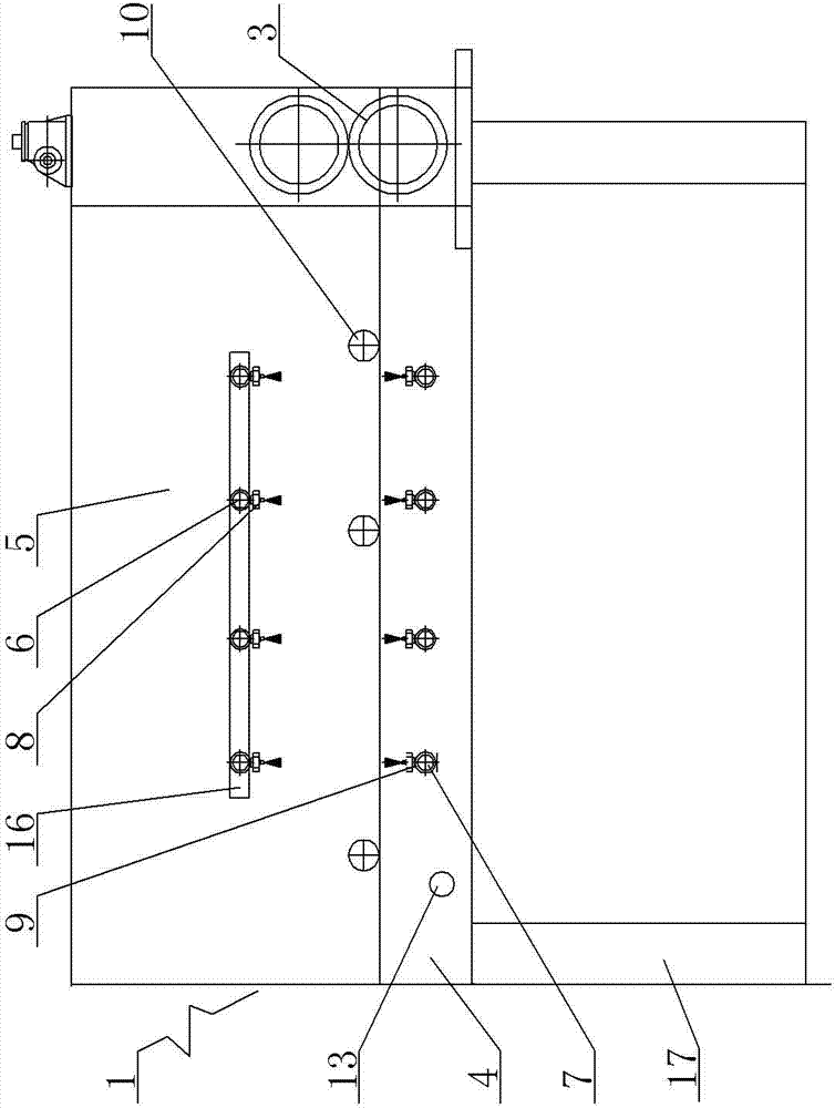
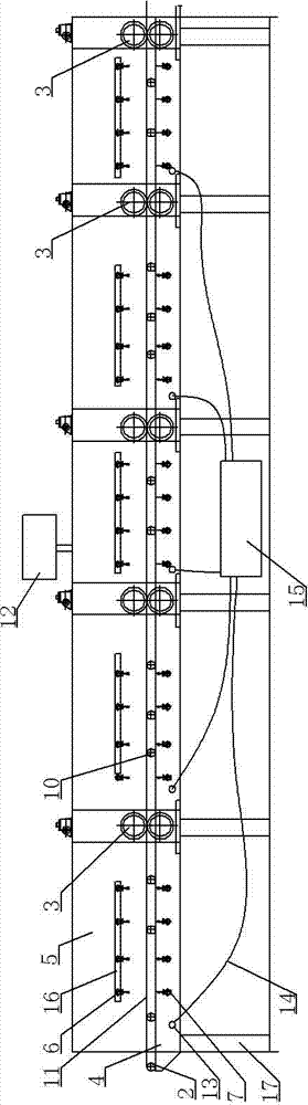
[0008] A degreasing cleaning spray tank, see figure 1 , figure 2 : It specifically includes five sections of degreasing and cleaning tank 1, the front end of the degreasing and cleaning tank 1 described in the first section is provided with a guide roller structure 2, and the rear end of the degreasing and cleaning tank 1 described in the last section is provided with a guide roller structure 3. The bottom of the degreasing and cleaning tank 1 in each section is a bracket 17, the middle part is a hot water storage tank 4, and the upper part is two side baffles 5. There is a guide pressure between the degreasing and cleaning tanks 1 in each two sections. The roller structure 3, the card groove 16 between the upper side baffles 5 is fitted with evenly distributed upper water pipes 6, and the evenly distributed lower water pipes 7 are arranged between the two side walls of the middle hot water storage tank 4 , the lower end surface of each of the upper water pipes 6 is evenly d...


PUM


Abstract

The invention provides a degreasing cleaning spraying tank, and the tank helps to shorten degreasing length, reduce land cost and improve degreasing efficiency, and further helps to improve the production efficiency of a whole production line. The tank comprises five oil-removing cleaning boxes; the front end of the first-segment oil-removing cleaning box is provided with a guide roller structure, and the last-segment oil-removing cleaning box segment is provided with a guide pressure-roller structure; a support is arranged at the bottom of each oil-removing cleaning box, a hot-water accumulation tank is arranged at the central part of each oil-removing cleaning box, and two baffle plates are arranged at two sides of the upper part of each oil-removing cleaning box; a guide pressure-roller structure is arranged between each two adjacent oil-removing cleaning boxes; uniformly-distributed upper water pipes are installed in a clamping groove between two baffle plates at the upper part of each oil-removing cleaning box in a clamping manner; uniformly-distributed lower water pipes are arranged at two side walls of the hot-water accumulation tank at the central part of each oil-removing cleaning box; and the lower end face of each upper water pipe is uniformly provided with upper nozzles, and the upper end face of each lower water pipe is uniformly provided with lower nozzles.

Description

technical field [0001] The invention relates to the technical field of hot-rolled steel coil processing lines, in particular to a degreasing cleaning spray tank. Background technique [0002] The existing degreasing of the strip steel is immersed in the degreasing tank, and the hot water is allowed to wash away the grease. However, due to the low pressure of the hot water, the length of the degreasing tank must be long enough to remove the grease on the strip steel. The land cost of the degreasing tank is high, and because the degreasing tank is long, the efficiency of degreasing is low, thereby making the production efficiency of the whole production line low. Contents of the invention [0003] In view of the above problems, the present invention provides a degreasing cleaning spray tank, which shortens the length of degreasing, reduces land costs, improves degreasing efficiency, and further improves the production efficiency of the entire production line. [0004] A...

Claims


Application Information

Patent Timeline
Patent Type & Authority Applications(China)
IPC IPC(8): C23G3/02
Inventor 秦加伦
Owner WUXI XINJIAYUAN METALLURGY MACHINERY MFG
Why Eureka
Try Eureka