
Strip for circular stamped parts

A stamping and circular technology, which is applied in the field of circular stamping strips, can solve the problems of low material utilization and increased processing costs, and achieve the effects of reducing processing costs, saving materials, and improving material utilization

Inactive Publication Date: 2014-04-30
SUZHOU MINICUT PRECISION ENG
View PDF5 Cites 0 Cited by
  • Summary
  • Abstract
  • Description
  • Claims
  • Application Information

AI Technical Summary

Problems solved by technology

Considering the convenience of the above-mentioned processing, the shape of the formed strip is generally rectangular, as shown in the attached figure 2 As shown, but in order to improve the processing efficiency, two rows of circular stamping parts are set in the strip, and the two rows of circular stamping parts are arranged alternately, which can save materials, as shown in the attached image 3 As shown, but the material utilization of the above two kinds of strips is low, which increases the processing cost

Method used


Image

  • Strip for circular stamped parts
  • Strip for circular stamped parts
  • Strip for circular stamped parts

Examples


Embodiment Construction

[0015] The present invention is described below in conjunction with accompanying drawing.

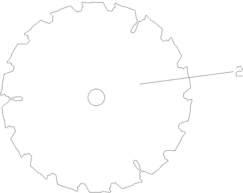
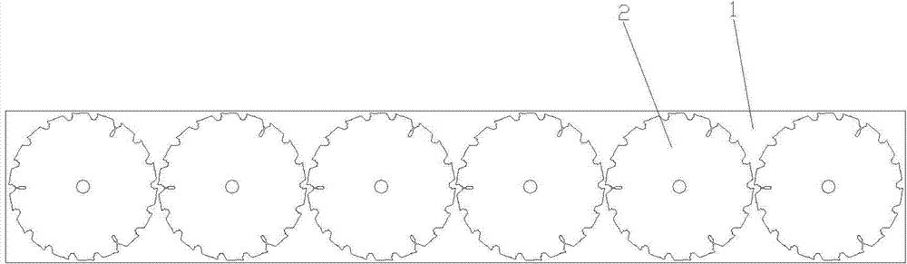
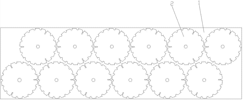
[0016] as attached Figure 4 The shown circular stamping part material strip according to the present invention includes a material strip body 1, and two rows of circular stamping parts 2 are arranged in the material strip body 1, and the two rows of circular stamping parts 2 are staggered Arranged, the horizontal section of the strip body 1 is a parallelogram; the two sides of the parallelogram in the length direction are inclined.

[0017] as attached Figure 5 As shown in the present invention, a circular stamping part material strip, since the horizontal section of the material strip body is a parallelogram, and the two sides in the length direction of the parallelogram are inclined, compared with the previous material strip, the area 3 is the material saved , greatly improving material utilization, reducing processing costs, and maximizing product benefits.

[0018] For the abov...


PUM


Abstract

The invention discloses a strip for circular stamped parts. The strip comprises a strip body. Two rows of circular stamped parts are arranged in the strip body and are staggered from each other, and the horizontal section of the strip body is in the shape of a parallelogram; two edges of the parallelogram in the length direction of the parallelogram are oblique; the quantities of the circular stamped parts of the two rows of circular stamped parts are equal to each other. The strip for the circular stamped parts has the advantages that the horizontal section of the strip body is in the shape of the parallelogram, the two edges of the parallelogram in the length direction of the parallelogram are oblique, accordingly, materials can be saved as compared with an existing rectangular strip, the material utilization rate can be greatly increased, the machining cost can be reduced, and the product effectiveness can be maximized.

Description

technical field [0001] The invention relates to a material strip of a circular stamping part, in particular to a material strip of a circular stamping part which can improve material utilization. Background technique [0002] as attached figure 1 For the stamping process of the circular stamping part shown, the circular stamping part strip is generally formed first, and then the circular stamping part strip is put into the blanking die for stamping processing. Considering the convenience of the above-mentioned processing, the shape of the formed strip is generally rectangular, as shown in the attached figure 2 As shown, but in order to improve the processing efficiency, two rows of circular stamping parts are set in the strip, and the two rows of circular stamping parts are arranged alternately, which can save materials, as shown in the attached image 3 As shown, but the material utilization of the above two kinds of strips is low, which increases the processing cost. ...

Claims


Application Information

Patent Timeline
Patent Type & Authority Applications(China)
IPC IPC(8): F16S1/08B21D47/00
Inventor 胡晓刚
Owner SUZHOU MINICUT PRECISION ENG
Features
  • Generate Ideas
  • Intellectual Property
  • Life Sciences
  • Materials
  • Tech Scout
  • Unparalleled Data Quality
  • Higher Quality Content
  • 60% Fewer Hallucinations
Learn More