Immunochromatographic detection device and method
An immunochromatographic detection and detection window technology, applied in the direction of measuring devices, analytical materials, instruments, etc., can solve the problems of unreliable reading results, complicated operation steps, easy to confuse test strips, etc., and achieve quantitative and intuitive display results , simple operation and low cost
- Summary
- Abstract
- Description
- Claims
- Application Information
AI Technical Summary
Problems solved by technology
Method used
Image
Examples
Embodiment 1
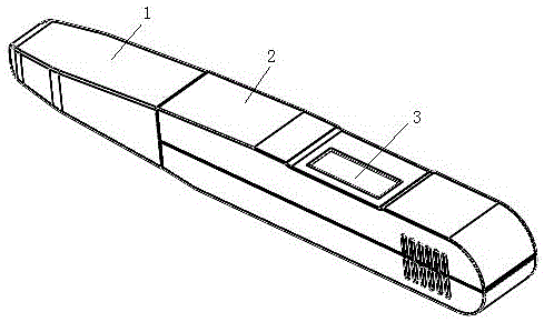
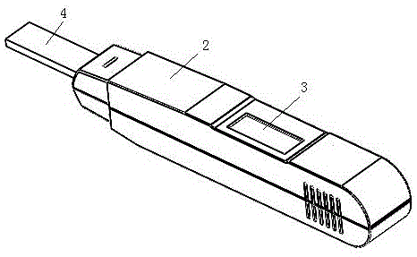
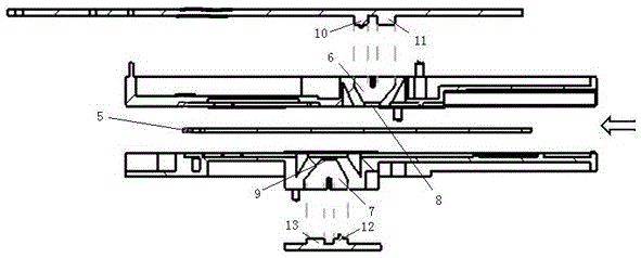
[0030] Such as figure 1 , figure 2 , image 3 As shown, the immunochromatographic detection device includes a housing 2, a cover 1 detachably connected to the housing, a liquid crystal display 3 disposed on the surface of the housing, a test strip 5 disposed inside the housing, and a measurement control circuit, the end of the housing is provided with a water-absorbing rod 4 for sample injection, one end of the water-absorbing rod is in contact with the test strip in the housing, and the other end of the water-absorbing rod extends from the inside of the housing to the end of the housing The casing is placed in the chamber formed by the cover and the end of the casing. When in use, the cover is removed from the housing, and the water-absorbing rod at the end of the housing is immersed in the liquid sample, so that the liquid sample flows along the water-absorbing rod onto the test strip.
[0031] The test strip 5 is a light-transmitting immunochromatographic test strip, w...
Embodiment 2
[0036] This embodiment provides an immunochromatographic detection method, and the device used in this embodiment is the same as that in Embodiment 1.
[0037] An immunochromatographic detection method, comprising the steps of:
[0038] 1. Provide the device described in Implementation 1.
[0039] 2. Put the liquid sample in contact with the test strip sample inlet (absorbent stick) at the end of the shell, the liquid sample flows onto the test strip, and the detection device is automatically activated.
[0040] 3. The light source placed in the optical path cavity of the detection area irradiates the detection area on the test strip, and the photodetector placed in the optical path cavity of the detection area detects the light reflected from the detection area, converts it into an electrical signal, and transmits it to the micro Controller board; the light source placed in the optical path cavity of the control area irradiates the control area on the test strip, and the pho...
PUM
 Abstract
Description
Claims
Application Information
 - R&D
- Intellectual Property
- Life Sciences
- Materials
- Tech Scout
- Unparalleled Data Quality
- Higher Quality Content
- 60% Fewer Hallucinations
Browse by: Latest US Patents, China's latest patents, Technical Efficacy Thesaurus, Application Domain, Technology Topic, Popular Technical Reports.
© 2025 PatSnap. All rights reserved.Legal|Privacy policy|Modern Slavery Act Transparency Statement|Sitemap|About US| Contact US: help@patsnap.com


