Method for detecting vision localization of QFP element

A detection method and visual positioning technology, applied in computer parts, instruments, characters and pattern recognition, etc., can solve the problems of high precision requirements, long consumption time, uneven image gray value, etc., to achieve high execution efficiency, high The effect of resolution and precision

Active Publication Date: 2014-04-30
宁波智能装备研究院有限公司
View PDF4 Cites 45 Cited by
  • Summary
  • Abstract
  • Description
  • Claims
  • Application Information

AI Technical Summary

Problems solved by technology

[0003] The present invention is to solve the problem that the traditional QFP component detection method has high requirements on the accuracy of the suction nozzle to pick up the components, the gray value of the image is uneven, the pins are ...

Method used


Image

  • Method for detecting vision localization of QFP element
  • Method for detecting vision localization of QFP element
  • Method for detecting vision localization of QFP element

Examples


specific Embodiment approach 1

[0029] Specific embodiment one: a kind of detection method for QFP element visual positioning of this embodiment is realized according to the following steps:

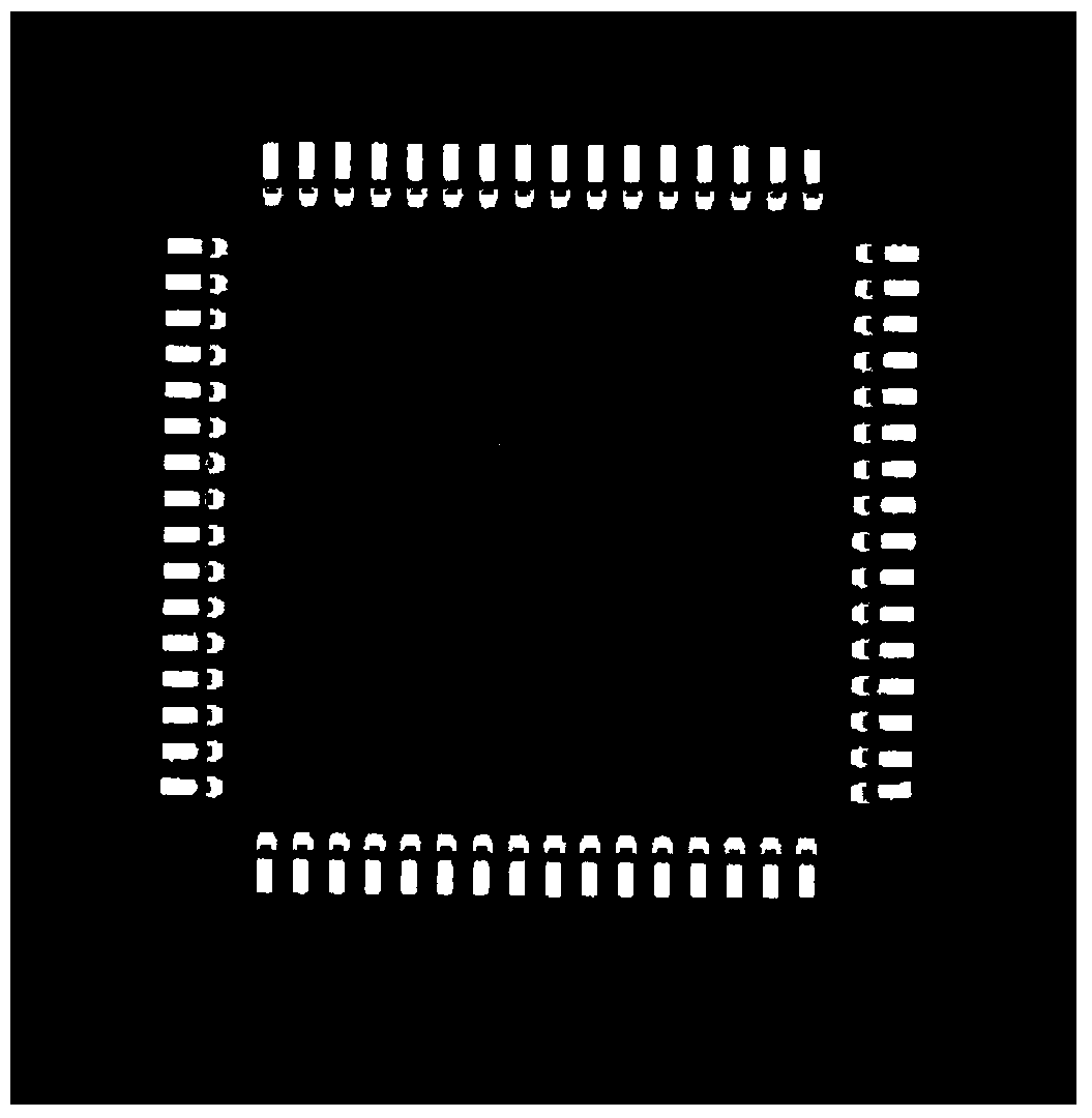
[0030] Step 1, using an optical lighting system to obtain a grayscale image of the QFP element;

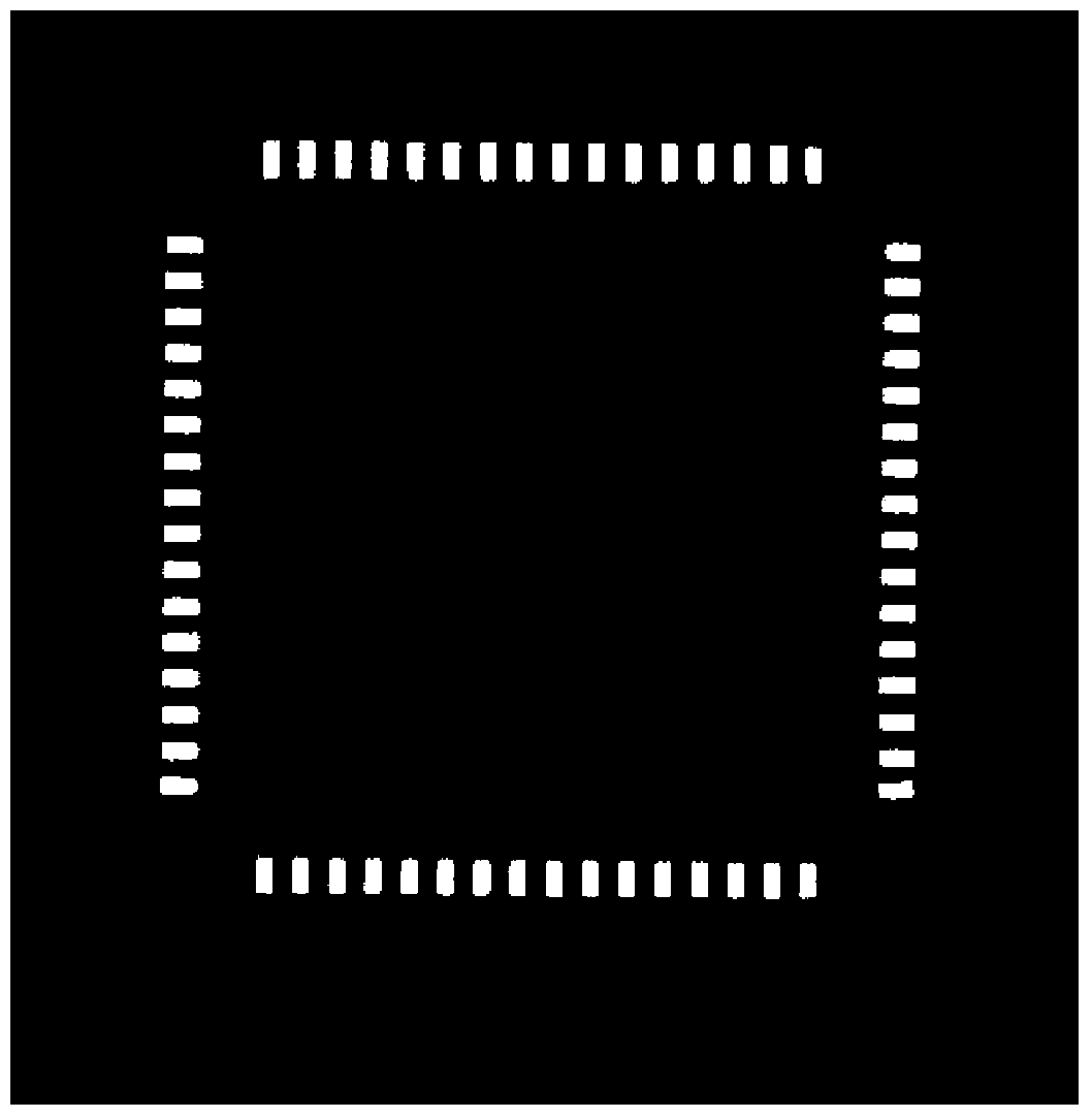
[0031] Step 2, preprocessing the image obtained in step 1 to filter out noise in the image;

[0032] Step 3, the image obtained in step 2 is processed by an automatic threshold segmentation method, and each connected region is marked in the generated binary image using a connected region marking algorithm, and the connected region marking algorithm is realized by a two-pass scanning method; and The marked connected region is set as the foreground;

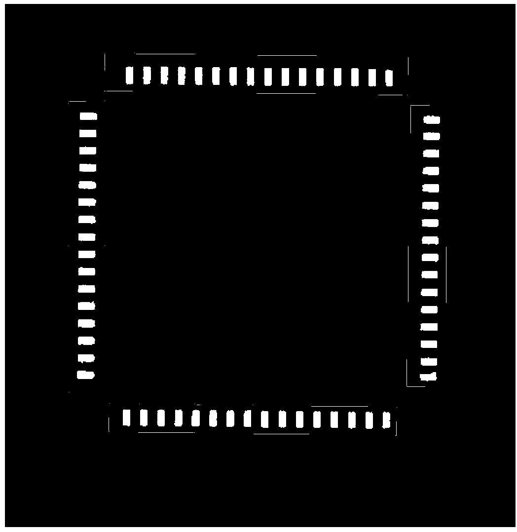
[0033] Step 4, count each connected region obtained in step 3, and calculate the area of ​​the connected region, filter out small connected regions, and retain the image at the end of the pin;

[0034] Step 5. Mark the connected area on the pin end image obtained in step 4. C...

specific Embodiment approach 2

[0046] Specific implementation mode two: this implementation mode is a further explanation to specific implementation mode one: the two-pass scanning method described in step three is specifically implemented according to the following steps:

[0047] (1), scan the binary image, obtain the temporary label, according to the connection rule of 8 neighbors in the foreground, set any pixel as f(x, y), and its temporary connected domain label array as label(x, y); Starting from the upper left corner, the image is scanned from top to bottom and from left to right. When the pixel point f(x, y) is scanned, the scanning of the upper and left pixels of the pixel point has been completed, and the pixel points of these pixels are The label value is known; if the pixel f(x,y) is connected to the upper and left pixels, then assign its label value to the smallest label among the upper and left pixels; if f(x,y) and these pixels are not connected, then add a new label and assign the label of ...


PUM


Abstract

The invention provides a method for detecting vision localization of a QFP element and relates to the field of vision localization and detection of the QFP element. The method aims at solving the problems that a traditional method for detecting the QFP element is high in requirement for accuracy of a suction nozzle suction element, image gradation values are not even, pins are broken in an image, and the overall morphology algorithm adopted to pin classification and repair is long in consumed time and poor in real-time performance. The technology mainly adopted by the method is that an image of the element to be detected is obtained, the binary image is scanned, connected regions are marked, the marked connected regions are divided and clustered, a mass center fitting boundary of each connected region is obtained, and then the rectangularity and the rotation angle of each connected region are calculated. The method for detecting vision localization of the QFP element is mainly used for pin detection and rotation angle detection of the QFP element.

Description

technical field [0001] The invention relates to the field of visual positioning and detection of QFP components. Background technique [0002] Among all rectangular lead components, QFP components have the highest requirements for positioning accuracy, and the algorithms for positioning and detection are the most complex. In the existing detection of QFP components, all pins of QFP components are classified based on the method of "first component pin scanning detection". However, this method needs to estimate in advance the position of the "first lead" of the component in the image according to the size of the component and the accuracy of the suction nozzle, thus putting forward higher requirements for the accuracy of the suction nozzle to pick up the component. When the angle error of the suction nozzle picking up the component is large, this method may fail. There are also algorithms that define four pin groups of NORTH, SOUTH, WEST, and EAST for components, and then gr...

Claims


Application Information

Patent Timeline
IPC IPC(8): G06K9/62G06K9/60
Inventor 高会军邱一帆周亚飞张欢欢张叶梅丁长兴孙昊
Owner 宁波智能装备研究院有限公司
Why Eureka
Try Eureka