Current transformer replacing device for power distribution cabinet

A technology for current transformers and power distribution cabinets is applied in the field of current transformer replacement devices, which can solve problems such as affecting work efficiency, inconvenient operation, and small space, and achieve the effects of reducing labor intensity, avoiding inconvenient replacement, and saving time.

Active Publication Date: 2014-04-30
STATE GRID CORP OF CHINA +3
View PDF5 Cites 4 Cited by
  • Summary
  • Abstract
  • Description
  • Claims
  • Application Information

AI Technical Summary

Problems solved by technology

[0004] However, in the prior art, if the current transformer of the power distribution cabinet needs to be replaced, the old current transformer needs to be manually disassembled, and then the new current transformer is assembled by hand. During the replacement process, the labor intensity of the workers is high and it is inconvenient to operate.
[0005] In addition, the above-mentioned manual hand-held replacement method is not conducive to quickly adjusting the assembly position of the new current transformer to the fixed beam, resulting in the need to manually hold the new current transformer for a long time during the replacement process, which affects work efficiency
At the same time, the manual manual replacement of the current transformer needs to be carried out in the power distribution cabinet, and the space in the power distribution cabinet is small, which is inconvenient for users to operate

Method used


Image

  • Current transformer replacing device for power distribution cabinet
  • Current transformer replacing device for power distribution cabinet
  • Current transformer replacing device for power distribution cabinet

Examples


Embodiment Construction

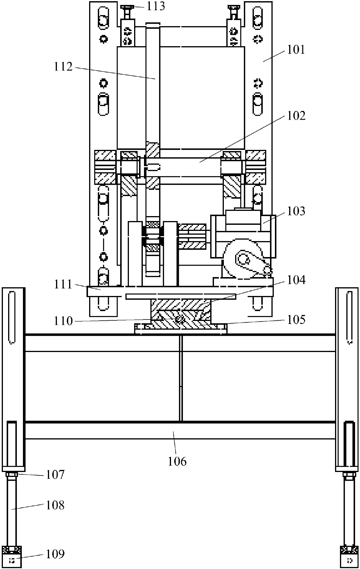
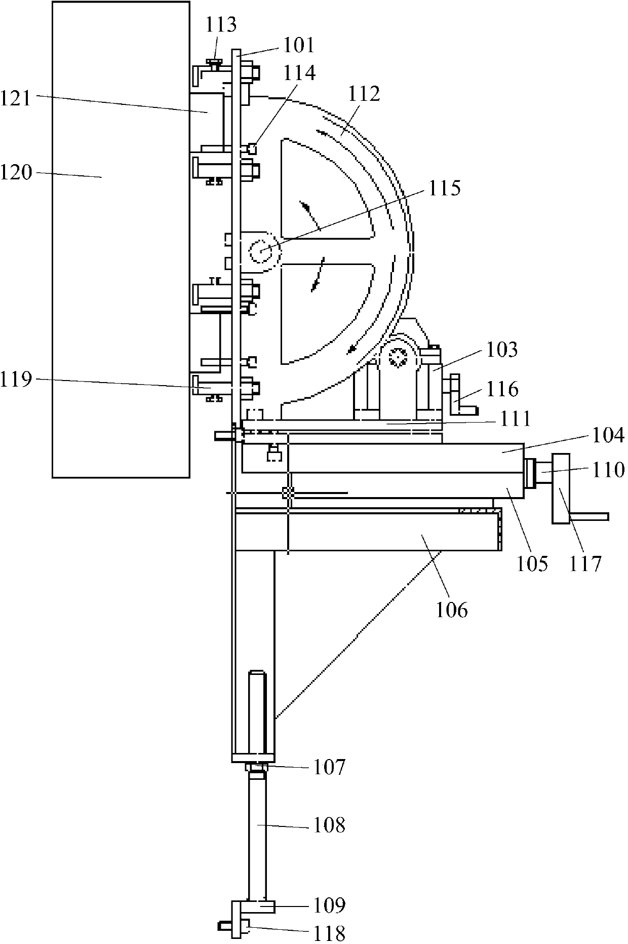
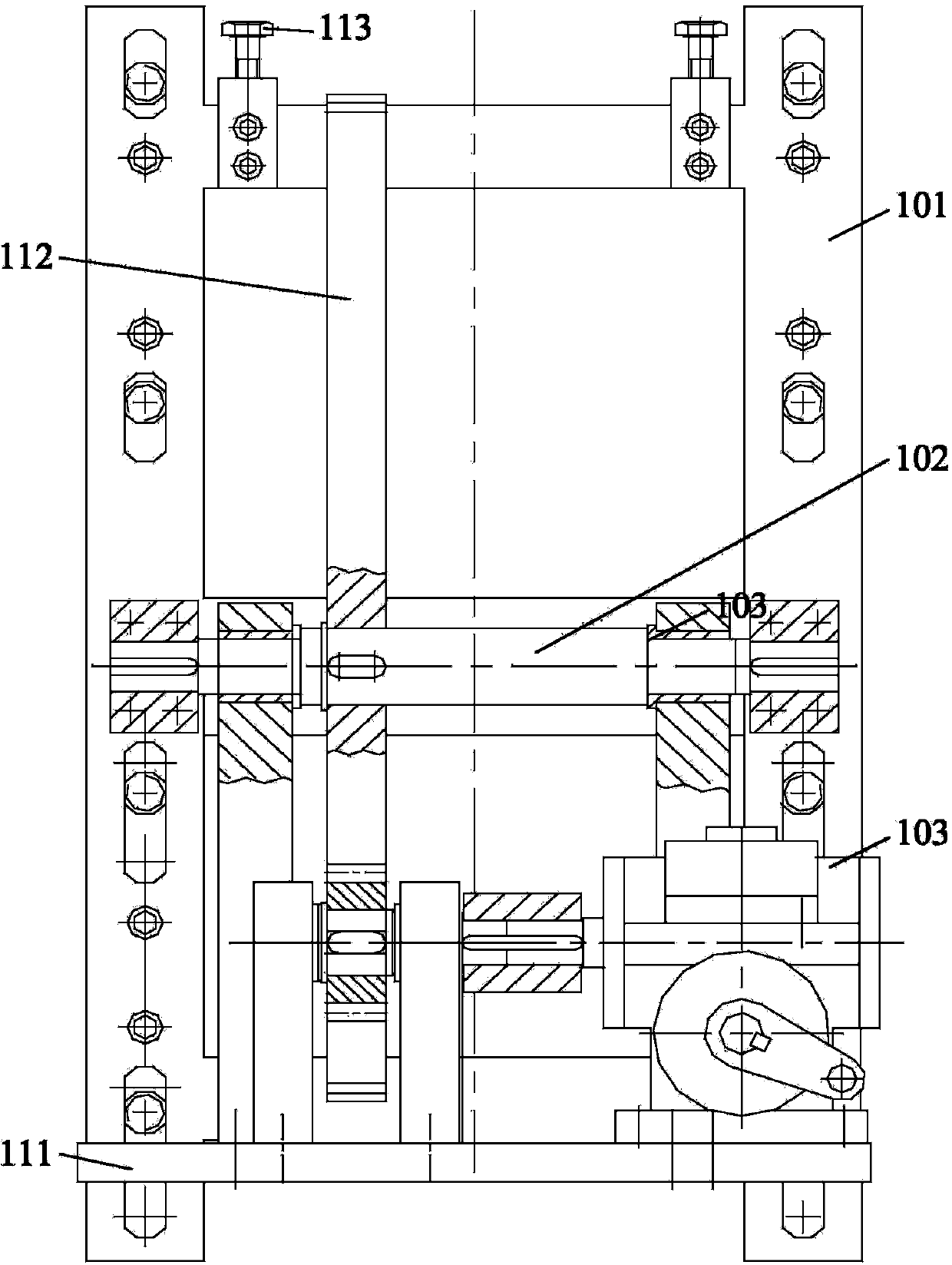
[0036] The embodiment of the invention discloses a current transformer replacement device for a power distribution cabinet, which can move the current transformer out of the power distribution cabinet, and use the support plate to support the current transformer horizontally, avoiding manual hand-holding of the current transformer , which is conducive to reducing the labor intensity of workers and is convenient for users to operate.

[0037] The following will clearly and completely describe the technical solutions in the embodiments of the present invention with reference to the accompanying drawings in the embodiments of the present invention. Obviously, the described embodiments are only some, not all, embodiments of the present invention. Based on the embodiments of the present invention, all other embodiments obtained by persons of ordinary skill in the art without making creative efforts belong to the protection scope of the present invention.

[0038] see Figure 1-Fig...


PUM


Abstract

The invention discloses a current transformer replacing device for a power distribution cabinet. The current transformer replacing device comprises an upper frame and a lower frame. The lower frame is used for being fixed to a shell of the power distribution cabinet. The upper frame can be movably arranged on the lower frame through a dragging assembly and is provided with a supporting board for horizontally supporting a current transformer of the power distribution cabinet. The supporting board can be arranged on the upper frame in a rotating mode and provided with a clamping assembly which is used for fixing a fixing beam of the power distribution cabinet. When the current transformer replacing device is used, firstly, the lower frame is fixed to the shell, the fixing beam is firmly fixed through the clamping assembly, and then the fixing beam is detached from the shell; secondly, the upper frame is driven to move towards the outside of the power distribution cabinet along the lower frame, and the supporting board is rotated to be horizontal; thirdly, the old current transformer is detached and a new current transformer is installed; finally, the supporting board is rotated to the original position, the upper frame is moved to the original position, and the fixing beam is assembled on the shell again. According to the current transformer replacing device, the current transformer is prevented from being held manually, labor intensity can be easily relieved, and operation is convenient.

Description

technical field [0001] The invention relates to the technical field of machinery industry, and more specifically relates to a current transformer replacement device for a power distribution cabinet. Background technique [0002] The power distribution cabinet is a general term for the motor control center, and it is used in occasions where the load is relatively scattered and the circuit is less. [0003] Currently, the power distribution cabinet is usually equipped with a current transformer and a fixed beam for fixing the above-mentioned current transformer, wherein the fixed beam is detachably arranged in the housing of the power distribution cabinet, and the current transformer is detachably fixed on the beam. [0004] However, in the prior art, if the current transformer of the power distribution cabinet needs to be replaced, the old current transformer needs to be manually disassembled, and then a new current transformer is held for assembly. During the replacement pr...

Claims


Application Information

Patent Timeline
Patent Type & Authority Applications(China)
IPC IPC(8): H02B3/00
Inventor 徐钰栋叶志华李正浩陈国磊潘锦良张魏邵文晋温旭辉陈阿赛徐承敏
Owner STATE GRID CORP OF CHINA
Why Eureka
Try Eureka