Production method for embedded permanent magnet rotor of tangential and radial resultant magnetic field driving motor

A technology for driving motors and permanent magnet rotors, which is applied in the manufacture of stator/rotor bodies, etc. It can solve the problems of irreversible demagnetization, reduced efficiency of driving motors, etc., and achieves the effects of compact structure, high magnetic field strength, and high output power

Inactive Publication Date: 2014-04-30
SHANDONG UNIV OF TECH
View PDF5 Cites 14 Cited by
  • Summary
  • Abstract
  • Description
  • Claims
  • Application Information

AI Technical Summary

Problems solved by technology

[0002] At present, most of the production methods of permanent magnet drive motor rotors used in electric vehicles adopt the permanent magnet external embedded structure, such as the existing technology, patent name: brushless DC motor rotor, patent number: ZL200920116549.1, discloses the following technical solutions, Including rotor core, rotating shaft and permanent magnet, the rotor core is composed of punched sheets and connected into one, the rotating shaft is fixedly connected with the rotor core, the outer surface of the rotor core is evenly distributed with an even number of T-shaped wedges, adjacent T Slots are formed between the shaped wedges, and the permanent magnets are correspondingly embedded in the slots. The permanent magnets of the rotor with this structure directly face the air gap. Under the action of the armature reaction of the impact current, irreversible demagnetization may occur. Once the permanent magnets are formed irreversible Demagnetization, the efficiency of the drive motor decreases, the power and torque drop rapidly, and its performance needs to be further improved

Method used


Image

  • Production method for embedded permanent magnet rotor of tangential and radial resultant magnetic field driving motor

Examples


Embodiment Construction

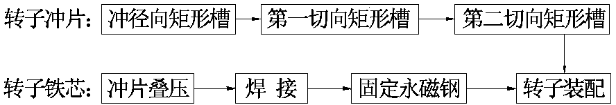
[0008] The present invention will be further described below in conjunction with accompanying drawing:

[0009] The production method of a permanent magnet rotor embedded in a tangential and radial synthetic magnetic field drive motor is characterized in that: punching and cutting a ring-shaped rotor punch, the rotor punch is evenly distributed with an even number of radial rectangular grooves running through the thickness of the rotor punch, the diameter There is a 1.5mm disconnected part between the outer end of the rectangular groove and the outer circle of the rotor punch, and a first tangential rectangular groove penetrating through the thickness of the rotor punch is provided between the inner ends of two adjacent radial rectangular grooves. Slots, the first tangential rectangular slots are used as magnetic isolation air gaps, the width of which is not less than 3mm, multiple first tangential rectangular slots are all tangent to the same circle, and are not connected to t...


PUM


Abstract

The invention provides a production method for an embedded permanent magnet rotor of a tangential and radial resultant magnetic field driving motor, and belongs to the technical field of automobile motor electric appliances. Pieces of rectangular permanent magnet steel are embedded into radial rectangular grooves and second tangential rectangular grooves of a rotor iron core respectively. Due to the fact that the tangential and radial resultant magnetic field driving motor is of a rotor magnetic bypass structure, the problem that irreversible demagnetization is generated when the permanent magnet steel bears the action of the armature reaction of an impact current can be effectively avoided, it is ensured that demagnetization does not happen on the permanent magnet steel, the magnetic field of the rotor of the driving motor is supplied by both the tangential magnetic field and the radial magnetic field, the magnetic field intensity is large, output power is high, and the embedded permanent magnet rotor has the advantages of being high in efficiency and power density, compact in structure, reliable in work and the like.

Description

technical field [0001] The invention provides a method for producing a permanent magnet rotor embedded in a tangential and radial synthetic magnetic field drive motor, which belongs to the technical field of automobile motors and electrical appliances. Background technique [0002] At present, most of the production methods of permanent magnet drive motor rotors used in electric vehicles adopt the permanent magnet external embedded structure, such as the existing technology, patent name: brushless DC motor rotor, patent number: ZL200920116549.1, discloses the following technical solutions, Including rotor core, rotating shaft and permanent magnet, the rotor core is composed of punched sheets and connected into one, the rotating shaft is fixedly connected with the rotor core, the outer surface of the rotor core is evenly distributed with an even number of T-shaped wedges, adjacent T Slots are formed between the shaped wedges, and the permanent magnets are correspondingly embe...

Claims


Application Information

Patent Timeline
Patent Type & Authority Applications(China)
IPC IPC(8): H02K15/03
Inventor 张学义杜钦君刘瑞军刘从臻尹红彬
Owner SHANDONG UNIV OF TECH
Why Eureka
Try Eureka