
pressure imaging sensor

An imaging sensor and pressure technology, applied in the direction of image communication, TV, color TV parts, etc., can solve the problems of easy violation of personal privacy, large amount of information, etc., achieve target extraction and pattern recognition with small calculation amount, wide application, Strong real-time effects

Active Publication Date: 2017-03-08
CHENGDU SEEKCON MICROWAVE COMM
View PDF3 Cites 0 Cited by
  • Summary
  • Abstract
  • Description
  • Claims
  • Application Information

AI Technical Summary

Problems solved by technology

But at the same time, due to the large amount of information, it brings a lot of useless calculations to the automatic extraction and recognition of target extraction and pattern recognition.
In addition, due to the large amount of information, the imaged object information is relatively complete, and it is easy to violate personal privacy.

Method used


Image

  • pressure imaging sensor
  • pressure imaging sensor
  • pressure imaging sensor

Examples


Embodiment Construction

[0028] The specific embodiments of the present invention will be described in detail below in conjunction with the accompanying drawings.

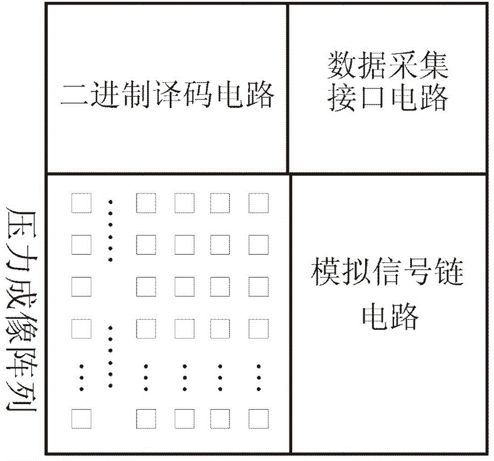
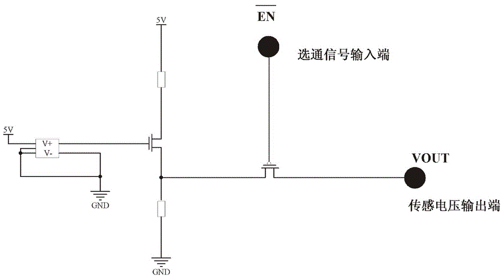
[0029] Pressure imaging sensor of the present invention, comprises a by 2 M ×2 N A pressure imaging array formed by arranging ×A pressure imaging pixels and a binary decoding circuit, M, N and A are natural numbers; a pressure imaging pixel includes a MEMS pressure sensor and a gating circuit, with a gating signal input terminal and a sensing voltage output terminal; A pressure imaging pixels form a pixel group, the gate signal input terminals of A pressure imaging pixels in a pixel group are connected together, and the transmission signals of A pressure imaging pixels in a pixel group The sensing voltage output terminals are not connected to each other as A sensing voltage output terminals; 2 M+N A pixel group shares A sensor voltage output terminal, 2 M+N There are 2 pixel groups M+N a strobe signal input terminal; the binary decodin...


PUM


Abstract

The invention discloses a pressure imaging sensor. Each pressure imaging pixel comprises an MEMS pressure sensor, a gating circuit, a gating signal input end and a sensing voltage output end. Each pixel set is composed of A pressure imaging pixels, the gating signal input ends of the A pressure imaging pixels of each pixel set are connected together, and the sensing voltage output ends of the A pressure imaging pixels of each pixel set are not connected with one another, and serve as the A sensing voltage output ends; the A sensing voltage output ends of each pixel set are shared by 2<M+N> pixel sets, and the 2<M+N> pixel sets are provided with 2<M+N> gating signal input ends in total; a binary system decoding circuit has (M+N) decoding input signals and 2<M+N> decoding output signals, wherein each decoding output signal is connected with the gating signal input ends of the corresponding pixel set. According to the pressure imaging sensor, the shape feature and the pressure feature of an imaged object can be effectively reserved, the amount of calculation of target extraction and the amount of calculation of mode recognition are small, real-time performance is good, reliability of mode recognition is high, concealment of an imaging device is good, and the pressure imaging sensor is widely applied.

Description

technical field [0001] The invention relates to the field of imaging technology, in particular to the field of pressure imaging, and specifically refers to a sensor that uses a MEMS pressure sensor array to form pressure imaging pixels, and obtains image information of a pressured object by collecting data from the pressure imaging sensor. Background technique [0002] With the continuous development of MEMS sensor technology, the original bulky sensors can be made very small, which is very convenient to form sensors into arrays, so as to realize the functions and technological breakthroughs that could not be realized before. At present, imaging technologies are mainly wave imaging technologies, such as visible light waves, infrared light waves, ultrasonic waves, and radar electromagnetic waves. The above-mentioned wave imaging technology has a large amount of information and reflects the information of the imaged object more comprehensively. But at the same time, due to th...

Claims


Application Information

Patent Timeline
Patent Type & Authority Patents(China)
IPC IPC(8): H04N5/335H04N5/341
Inventor 颜福才
Owner CHENGDU SEEKCON MICROWAVE COMM
Learn More