Chain shaft of chain and manufacturing method thereof

A manufacturing method and chain shaft technology, which are applied to the lubrication of belts/chains/gears, chain elements, and engines, can solve the problems of wear and service life of chain components, and the lubrication effect is not easy to last and shorten, so as to increase the oil storage space, The effect of improving smoothness and wear resistance, and prolonging service life

Inactive Publication Date: 2014-05-07
YUEMENG ENTERPRISE
View PDF5 Cites 3 Cited by
  • Summary
  • Abstract
  • Description
  • Claims
  • Application Information

AI Technical Summary

Problems solved by technology

[0004] However, because the outer peripheral surface of the chain shaft in the past is a smooth and flat surface, when the lubricating oil is added to the joint part of the c

Method used


Image

  • Chain shaft of chain and manufacturing method thereof
  • Chain shaft of chain and manufacturing method thereof
  • Chain shaft of chain and manufacturing method thereof

Examples


Embodiment Construction

[0026] Below in conjunction with accompanying drawing and embodiment the present invention is described in detail:

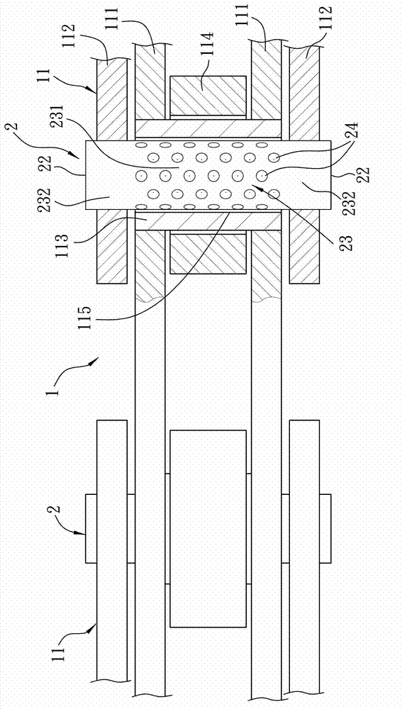
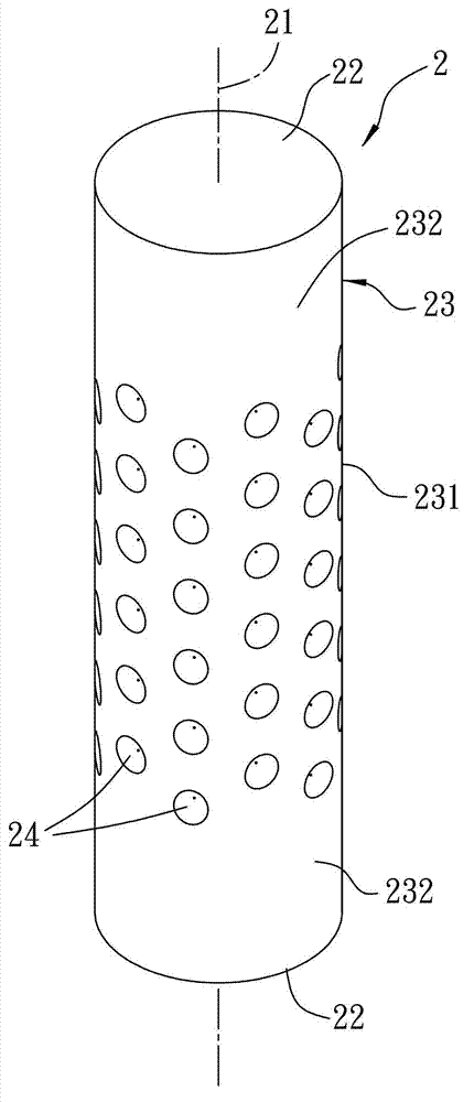
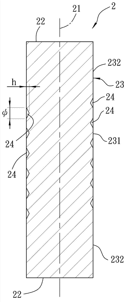
[0027] refer to figure 1 , figure 2 and image 3 , the preferred embodiment of the chain shaft 2 of the present invention is that several are installed at intervals on a chain 1, and the chain 1 includes several ring-shaped series connection units 11 connected in series from head to tail, each of which is connected in series In addition to the chain shaft 2, the unit 11 also includes two inner chain pieces 111 that are sheathed on the outer periphery of the chain shaft 2 at intervals and oppositely, and two inner chain pieces 111 that are respectively located outside the inner chain pieces 111 and are connected to the chain shaft 2. Outer chain pieces 112 at both ends, a bushing 113 sleeved on the periphery of the chain shaft 2 and both ends combined with the inner chain piece 111 , and a bushing 113 sleeved on the periphery of the bushing 113 and located on ...


PUM

PropertyMeasurementUnit
Diameteraaaaaaaaaa
Depthaaaaaaaaaa
Diameteraaaaaaaaaa

Abstract

The invention relates to a chain shaft of a chain and a manufacturing method of the chain shaft. The chain shaft of the chain comprises two end faces located at the two opposite ends of the central axis in a spaced mode, a peripheral face around the central axis and a plurality of oil storage grooves, wherein the oil storage grooves surround the central axis respectively and sink from the peripheral face to the central axis at intervals, and the periphery of each oil storage groove is closed and is not communicated with the end faces and the other oil storage grooves. When the chain shaft is installed on the chain, the oil storage grooves can enlarge the oil storage space of the chain so as to improve the smoothness and the abrasion resistance in operation of the chain, and meanwhile the service life of the chain can be prolonged. The manufacturing method of the chain shaft of the chain includes the blank knurling step, a blank is knurled in a rolling mode to form the chain shaft, and thus the chain shaft is easy to machine and form in the manufacturing process.

Description

technical field [0001] The invention relates to a chain shaft and a manufacturing method thereof, in particular to a chain shaft of a chain with several oil storage grooves recessed on the outer peripheral surface and a manufacturing method thereof. Background technique [0002] Generally, the design of the chain is usually composed of several series units connected in series to form a ring shape. Each series unit roughly includes: two inner chain pieces facing each other at intervals, and two inner chain pieces located on the outside of the inner chain pieces respectively. an outer chain piece, a chain shaft inserted into the inner chain piece and connected to the outer chain piece at both ends, and a bushing used to combine with the inner chain piece and sleeved on the periphery of the chain shaft, And a chain roller sleeved on the periphery of the bush. [0003] The bushing and the inner chain piece form a combined body, the chain shaft and the outer chain piece are conn...

Claims


Application Information

Patent Timeline
IPC IPC(8): F16G15/00F16N1/00B21D35/00
Inventor 吴能家
Owner YUEMENG ENTERPRISE
Why Eureka
Try Eureka