Damper assembly for reducing combustion-chamber pulsation

A technology of muffler and burner, applied in the direction of combustion chamber, continuous combustion chamber, combustion method, etc., can solve problems such as unpopular solutions

Active Publication Date: 2014-05-07
ANSALDO ENERGIA SWITZERLAND AG
View PDF14 Cites 11 Cited by
  • Summary
  • Abstract
  • Description
  • Claims
  • Application Information

AI Technical Summary

Problems solved by technology

This solution is not popular because of the large volume required for the low frequency muffler

Method used


Image

  • Damper assembly for reducing combustion-chamber pulsation
  • Damper assembly for reducing combustion-chamber pulsation
  • Damper assembly for reducing combustion-chamber pulsation

Examples


specific Embodiment

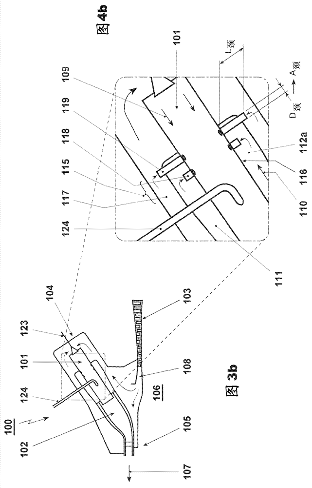
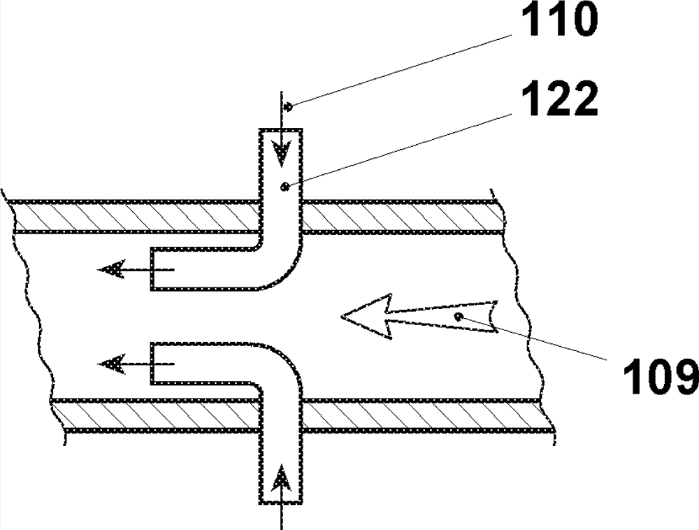
[0083] In a cross-flow configuration, the oscillating gaseous fuel is injected perpendicular to the flow of oxidant.

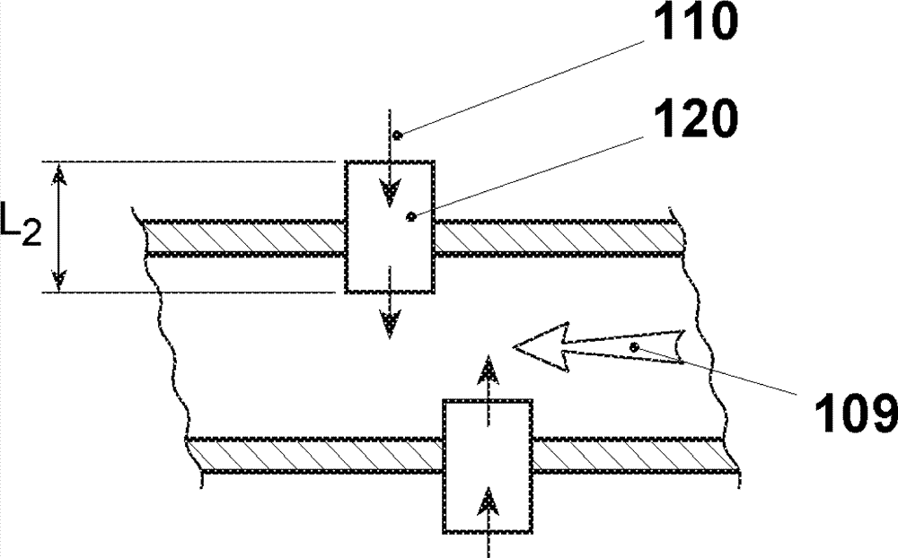
[0084] In an in-line configuration, an oscillating gaseous fuel is injected parallel to the flow of oxidant.

[0085] The oscillating gaseous fuel is injected at an oblique angle between 0° and 90° relative to the oxidant flow.

[0086] EP 0 646 705 A1 relates to a method for establishing part-load operation in a gas turbine bank with sequential fuel, EP 0 646 704 A1 relates to a method for controlling a gas turbine installation equipped with two combustion chambers, and

[0087] EP 0 718 470 A1 relates to a method for operating a gas turbine equipped with two combustion chambers while providing part-load operation, which also forms an integral part of the present description.

[0088] Some compressed air 108 is tapped off as high pressure cooling air, fed as cooling air to the primary and / or secondary combustors or recooled by a high pressure cooling air coo...


PUM


Abstract

The invention concerns a damper assembly (112) for reducing combustion-chamber pulsation arising inside a gas turbine (100), wherein the gas turbine (100) essentially comprises at least one compressor (103), a primary combustor (101) which is connected downstream to the compressor (103), and the hot gases of the primary combustor (101) are admitted at least to an intermediate turbine or directly or indirectly to a secondary combustor (102). The hot gases of the secondary combustor (102) are admitted to a further turbine (105) or directly or indirectly to an energy recovery, wherein at least one combustor is arranged in a can-architecture. At least one combustor liner comprising air passages (114), wherein at least one of the air passages (114) is formed as a damper neck (113). The damper neck (113) being actively connected to a damper volume (112), and the damper volume (112) is part of a connecting duct extending between a compressor air plenum and the combustor.

Description

technical field [0001] The invention relates to a method for operating a gas turbine with injection of dilution air into a combustion chamber. The invention furthermore relates to a gas turbine for carrying out a method for operating a gas turbine with injection of a diluent into a combustion chamber. Background technique [0002] The injection of the dilution air into the combustion chamber of the gas turbine preferably takes place downstream of the burner. [0003] To protect the environment, CO emissions from gas turbine engines need to be reduced. Such emissions are known to occur without sufficient time in the combustion chamber to ensure oxidation of CO to CO 2 and / or this oxidation is locally quenched due to contact with cold areas in the burner. Because the combustion temperature is lower at part load and CO is oxidized to CO 2 The process slows down, so CO emissions generally tend to increase under these conditions. [0004] In addition to low emissions, a stab...

Claims


Application Information

Patent Timeline
Patent Type & Authority Applications(China)
IPC IPC(8): F23R3/38F23R3/58
CPCF02C6/02F23M99/005F23R2900/03341F23R3/002F05D2260/964F23R2900/00014F23R3/06F23M20/005Y02E20/16F02C7/00F02C7/045F02C3/14F23R3/42F05D2220/32F05D2240/35F23R3/346
Inventor M.R.博希恩J.赫拉特B.舒尔曼斯
Owner ANSALDO ENERGIA SWITZERLAND AG
Why Eureka
Try Eureka