A gas laser fault detection system and its detection method

A gas laser and fault detection technology, which is applied in the direction of instruments, measuring electronics, and measuring devices, can solve problems such as low maintenance efficiency, failure to discharge, and difficult detection, and achieve low maintenance costs, avoiding the expansion of faults, and high maintenance efficiency. Effect

Active Publication Date: 2016-04-06
GLORYMV ELECTRONICS
View PDF6 Cites 2 Cited by
  • Summary
  • Abstract
  • Description
  • Claims
  • Application Information

AI Technical Summary

Problems solved by technology

However, since gas lasers work in a high-voltage environment, they are prone to self-breakdown and undischargeable faults, but detection is relatively difficult. Basically, maintenance personnel are relied on to judge faults based on test data and actual measurements, and the maintenance efficiency is relatively low.

Method used


Image

  • A gas laser fault detection system and its detection method
  • A gas laser fault detection system and its detection method

Examples


Embodiment Construction

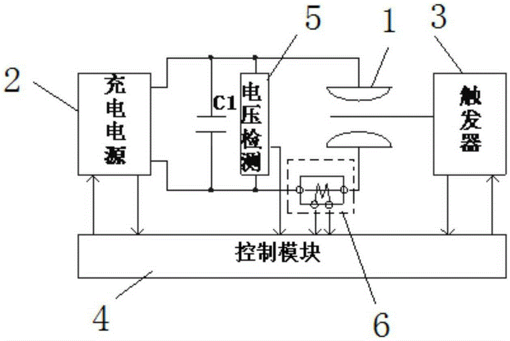
[0015] Such as figure 1 A gas laser fault detection system shown includes a laser 1, a charging power supply 2 connected to the laser 1, a trigger 3 that triggers the conduction of the laser 1, a control module 4 connected to the charging power supply 2 and the trigger 3, and a charging The energy storage capacitor C1 connected to the power source 2, the voltage detection unit 5 is connected to both ends of the energy storage capacitor C1, the current detection unit 6 is connected between the energy storage capacitor C1 and the laser 1, the voltage detection unit 5 and the current detection unit 6 are respectively connected with the control Module 4 is connected.

[0016] The control module 4 is used for judging the location of the fault by controlling the timing relationship of capacitor voltage detection, current detection, charging power supply and trigger. The control module can adopt control modules such as single-chip microcomputer, DSP, PLC.

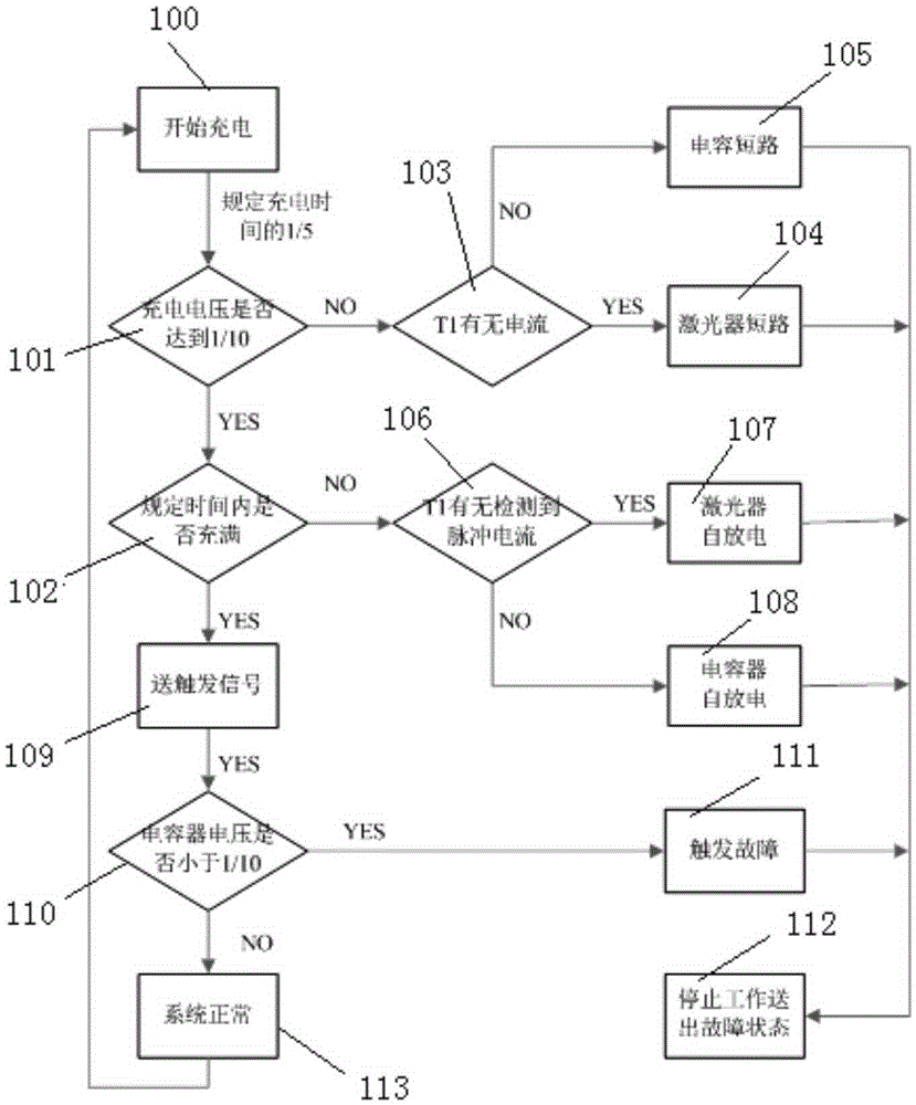
[0017] A fault detection...


PUM


Abstract

The invention discloses a gas laser failure detecting system and a detecting method thereof. The gas laser failure detecting system comprises the components of: a laser, a charging power supply which is connected with the laser, a trigger which triggers conduction of the laser, a control module which is connected with the charging power supply and the trigger respectively, and an energy storage capacitor which is connected with the charging power supply. Two ends of the energy storage capacitor are connected with a voltage detecting unit. A current detecting unit is connected between the energy storage capacitor and the laser. The voltage detecting unit and the current detecting unit are respectively connected with the control module. The control module is used for determining failure position through detecting capacitor voltage and current and controlling sequential relationship between the charging power supply and the trigger. The gas laser failure detecting system with the structure and the method have the following advantages: 1. quickly determining failure position, realizing a target of quick maintenance, simultaneously preventing failure enlargement; and 2. realizing high maintenance efficiency and low maintenance cost.

Description

technical field [0001] The invention relates to the technical field of gas lasers, in particular to a gas laser fault detection system and a detection method thereof. Background technique [0002] Gas lasers are lasers with gas or steam as the working substance. The lasers are widely used because of their advantages such as high conversion efficiency, simple structure, and low cost. However, since gas lasers work in a high-voltage environment, they are prone to self-breakdown and failure to discharge, but detection is difficult. Basically, maintenance personnel are relied on to judge faults based on test data and actual measurements, and maintenance efficiency is relatively low. Contents of the invention [0003] The technical problem to be solved by the present invention is to provide a gas laser fault detection system and its detection method for quickly judging the fault location and realizing rapid maintenance in view of the deficiencies in the prior art. [0004] In ...

Claims


Application Information

Patent Timeline
Patent Type & Authority Patents(China)
IPC IPC(8): G01R31/00G01R31/02
Inventor 刘林宫龙程辉潘传杰
Owner GLORYMV ELECTRONICS
Why Eureka
Try Eureka