Suspension device and microgravity experimental method applied to interior of space capsule

A technology of suspension device and experimental method, which is applied in the field of microgravity science, to achieve the effect of wide application range, simple realization and good microgravity environment

Active Publication Date: 2014-05-07
TECH & ENG CENT FOR SPACE UTILIZATION CHINESE ACAD OF SCI
View PDF6 Cites 25 Cited by
  • Summary
  • Abstract
  • Description
  • Claims
  • Application Information

AI Technical Summary

Problems solved by technology

[0019] The technical problem to be solved by the present invention is to provide a suspension device and a microgravity e

Method used


Image

  • Suspension device and microgravity experimental method applied to interior of space capsule
  • Suspension device and microgravity experimental method applied to interior of space capsule
  • Suspension device and microgravity experimental method applied to interior of space capsule

Examples


Embodiment 1

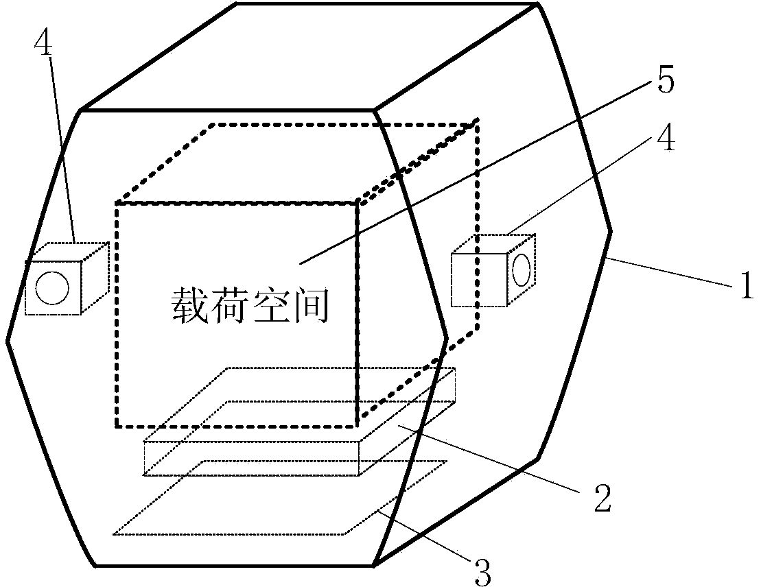
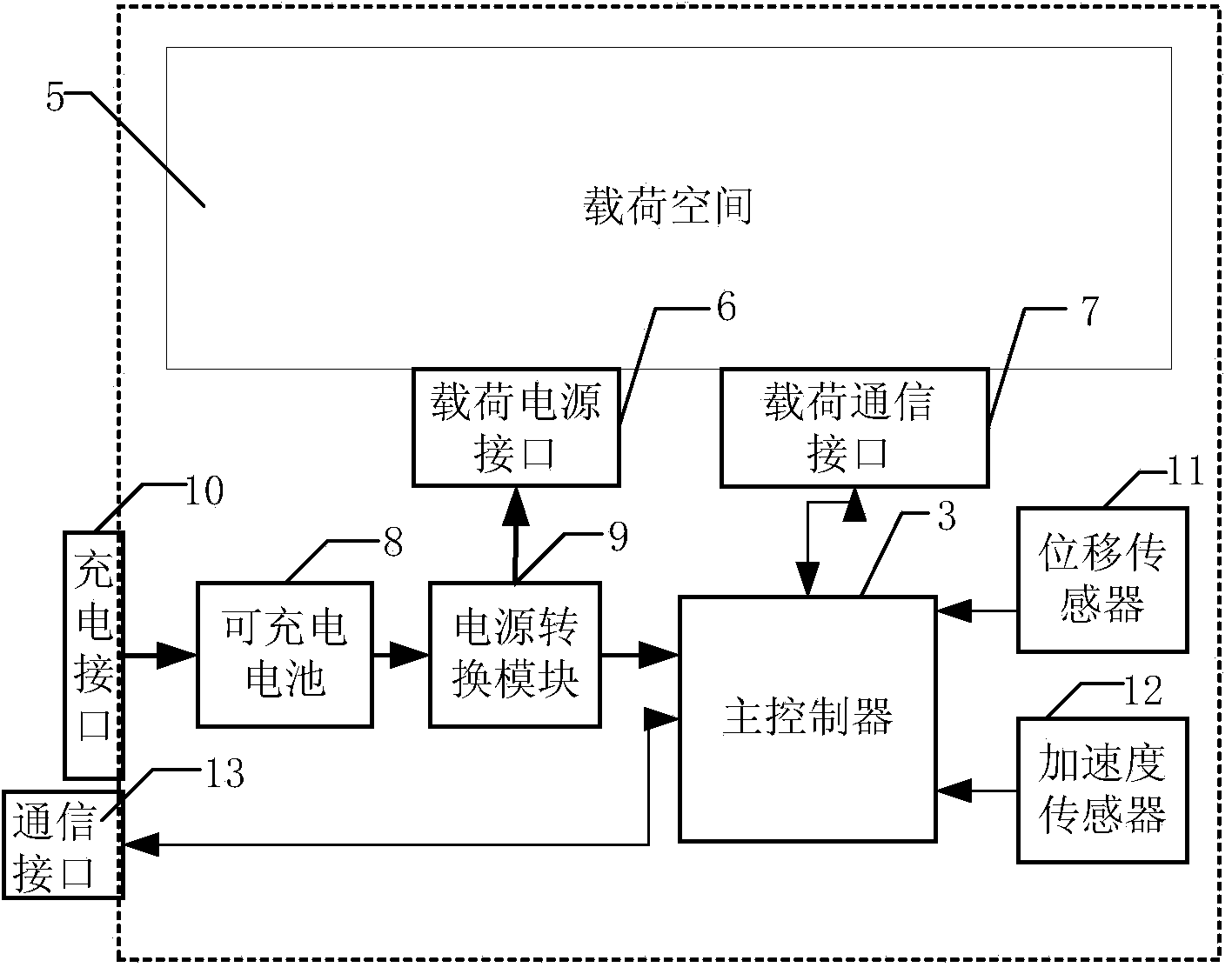
[0048] Such as figure 1 and figure 2 As shown, this embodiment provides a suspension device, including a body 1 and a power supply 2 placed in the body, a main controller 3, a sensor 4 and a load space 5, and the load power interface 6 and the load power interface 6 are arranged in the load space 5. The communication interface 7, the load power supply interface 6 and the load communication interface 7 are collectively referred to as the load interface; the power supply 2 is connected to the main controller 3 for supplying power to the main controller 3, and the power supply 2 is connected to the load power supply at the same time The interface 6 is used to supply power to the experimental load; the main controller 3 is connected to the load communication interface 7 for realizing mutual communication with the experimental load; the sensor 4 is connected to the main controller for collecting the The information is sent to the main controller 3 for processing. It should be no...

Embodiment 2

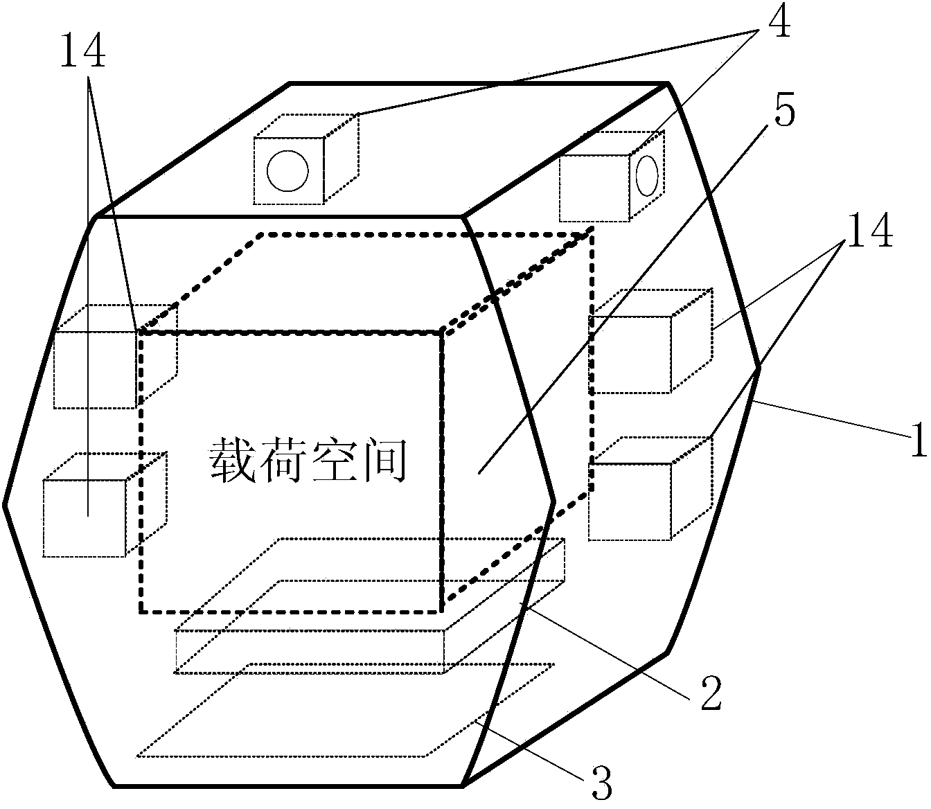
[0052] Embodiment 2 On the basis of the levitation device described in Embodiment 1, the design of a micro-propeller is added. Such as image 3 and Figure 4 As shown, in the levitation device described in the second embodiment, a micro-propeller 14 and a propulsion controller 15 are also installed in its body, and the micro-propeller 14 is connected with the main controller 3 through the propulsion controller 15, and is connected and installed at the same time. The nozzle 16 outside the main body is used to propel the nozzle 16 under the regulation of the main controller 3 and the propulsion controller 13 to operate, so as to ensure that the suspension device does not collide with the bulkhead.

[0053] The electronic structure of the suspension device is as Figure 4 As shown, compared with Embodiment 1, the suspension device has more micro-propellers 14 (working fluid), propulsion controller 15 and nozzle 16, and the micro-propellers must use the non-polluting gas in the ...


PUM

PropertyMeasurementUnit
Diameteraaaaaaaaaa

Abstract

The invention relates to a suspension device which comprises a body, a power source, a master controller, a sensor, a load power source interface, a load communication interface and load space. The power source, the master controller, the sensor, the load power source interface, the load communication interface and the load space are arranged in the body. An experiment load is installed in the load space, and the purposes that power is supplied to the experiment load by the power source, and the experiment load is communicated with the master controller are achieved through the load power source interface and the load communication interface. The sensor collects and sends suspension device information into the master controller to be processed. The invention further discloses a microgravity experiment method which includes the steps that the scientific experiment load is installed in the load space; the suspension device is arranged in a space capsule, a release gear is used for performing releasing freely at the minimal initial speed, and when the suspension device is in a complete weightlessness state, a scientific experiment is started; the scientific experiment load is recycled, and the suspension device is stopped in a stopping platform to be fixed and charged. According to the suspension device and the microgravity experiment method, the complete space in the capsule and astronaut resources are fully utilized, achieving is easy, cost is low, and a high microgravity level can be reached.

Description

technical field [0001] The invention relates to the field of microgravity science, in particular to a suspension device and a microgravity experiment method applied in a space capsule. Background technique [0002] Scientific experiments conducted in a state of weightlessness help to better explore physical laws and analyze natural phenomena, which is called microgravity science. Microgravity science includes many fields such as microgravity fluid physics, microgravity combustion, material science, biotechnology and basic physics, and has given birth to many major scientific progress and technological breakthroughs. [0003] Microgravity experiments are mainly carried out on the ground through free fall facilities (drop towers, falling wells), parabolic aircraft, microgravity sounding rockets, and high-altitude balloon drop bomb bays. The time is relatively short and the level of microgravity is not high. The use of space vehicles for microgravity experiments has a long-ter...

Claims


Application Information

Patent Timeline
IPC IPC(8): G09B23/10
Inventor 董文博高玉娥张建泉吕世猛何建华李宗峰刘伟
Owner TECH & ENG CENT FOR SPACE UTILIZATION CHINESE ACAD OF SCI
Why Eureka
Try Eureka