
Consistent localizer captures

A locator and zero position technology, applied in the field of continuous locator capture

Active Publication Date: 2014-05-07
THE BOEING CO
View PDF7 Cites 4 Cited by
  • Summary
  • Abstract
  • Description
  • Claims
  • Application Information

AI Technical Summary

Problems solved by technology

Current aircraft systems do not initiate locator capture until the linear portion of the locator beam (i.e. the course guidance segment) is reached and are therefore prone to large overshoots

Method used


Image

  • Consistent localizer captures
  • Consistent localizer captures
  • Consistent localizer captures

Examples


Embodiment Construction

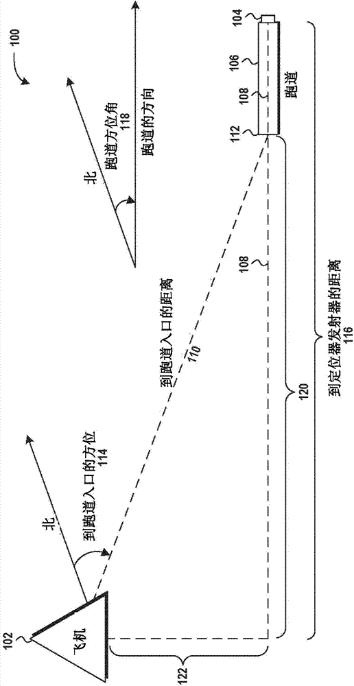
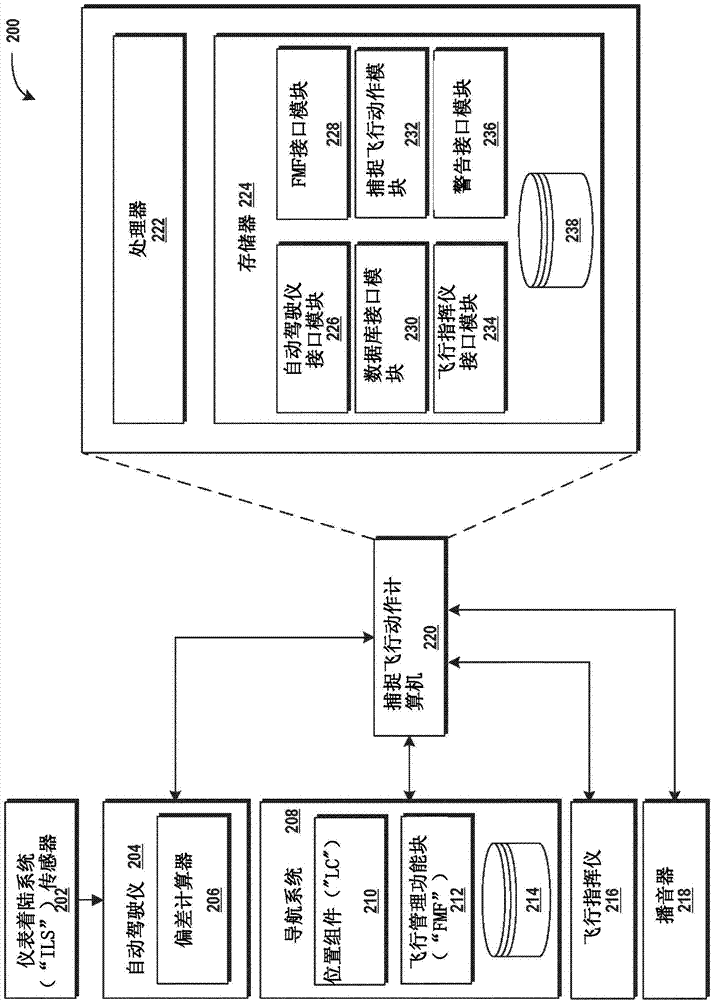
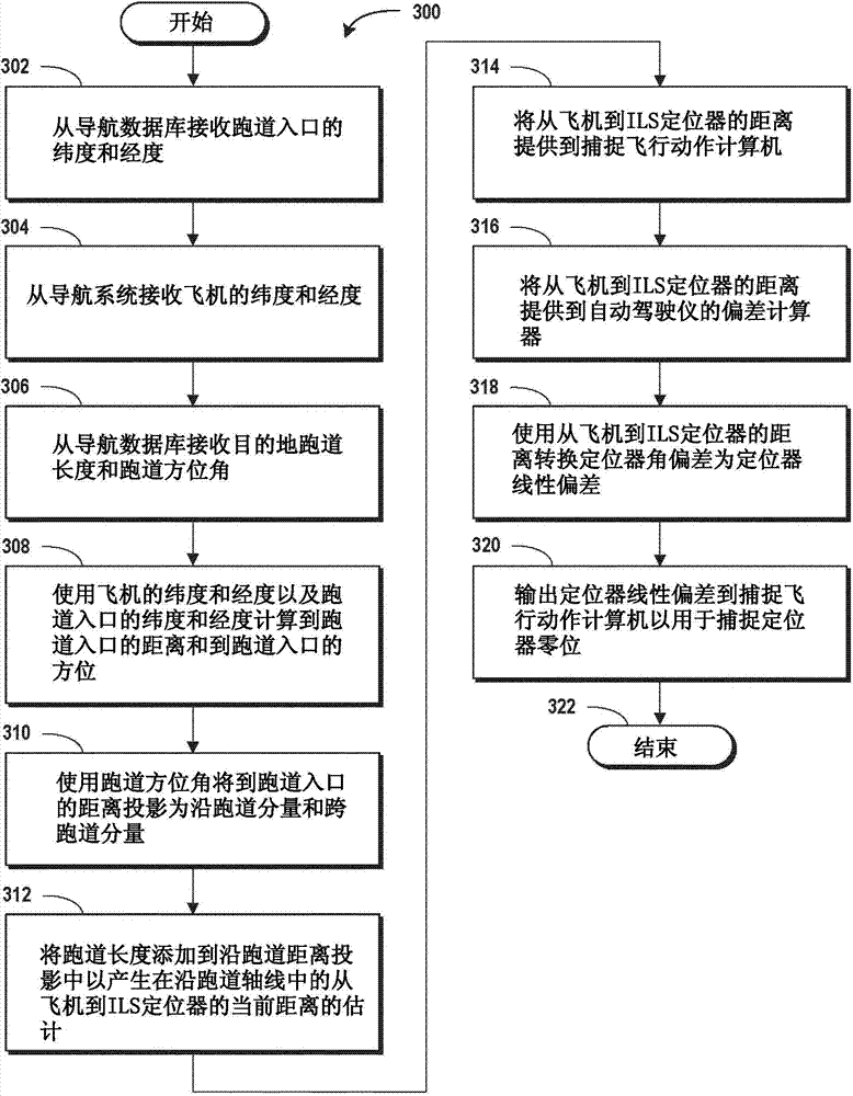
[0016] The following detailed description is directed to the concepts and techniques of persistent locator capture. According to the concepts and techniques described herein, information about the aircraft's current location (e.g., latitude and longitude) and the location of the destination runway (e.g., latitude and longitude) applicable onboard the aircraft is used to determine a more accurate A distance measurement used to convert instrument landing system ("ILS") bias from intrinsic angular bias to linear bias, thus enhancing locator acquisition performance and stability. Before describing the figures, some important details of the current ILS will be described to help discern the novel concepts and techniques for persistent locator capture presented herein.

[0017] As mentioned above, ILS guidance is inherently angled and is provided only in the narrow region known as the course guidance section where the angular offset received by the aircraft correctly reports the airc...


PUM


Abstract

Instrument Landing System ("ILS") localizer captures have historically been prone to performance degradations based upon erroneous estimates of the localizer deviation and deviation rate. The angular nature of the ILS beam and the relatively narrow trusted linear course guidance sector of the beam are the primary causes of many such issues. It is highly desirable to convert the angular guidance data into a rectilinear form when used by an autopilot and / or flight director systems, the latter of which allows for more consistent stability and performance with respect to distance to runway threshold. Systems and methods disclosed herein are for accurately converting angular localizer data into rectilinear localizer data, thus allowing for improved localizer capture performance and stability.

Description

Background technique [0001] An instrument landing system ("ILS") is a system that supports high-precision guidance of an aircraft approaching and landing on a runway. An ILS typically includes a transmitter and antenna array on the ground, a receiver and antenna on the aircraft, and a display to the flight attendant on the aircraft. An autopilot and / or flight director may also be used on the aircraft. [0002] The part of the ILS that provides lateral guidance is called the locator. Provide vertical guidance with slide down sections. The localizer and glide section provide the aircraft with an indication of its separation from the desired approach path in the form of an angular error known as the ILS angular deviation. [0003] An aircraft preparing to perform a landing approach must be flying on a flight path that intersects the locator. As the aircraft approaches the desired approach path (ie, the zero position of the locator), the aircraft performs a turn to capture sai...

Claims


Application Information

Patent Timeline
IPC IPC(8): G05D1/06G01S1/16G01S19/15G01S19/39B64D45/04
CPCG01S19/15G01S1/16G05D1/0676G08G5/025
Inventor A·R·胡克斯
Owner THE BOEING CO
Learn More