Unloading Composite Guide Rail Structure of Inclined Beam

A beam and guide rail technology, applied in the field of machine tools, can solve the problems that the bearing capacity of the composite guide rail is not large enough, the effect of use is not ideal, and the movement is not stable enough, so as to achieve the effect of large bearing capacity, ideal use effect and structural optimization.

Inactive Publication Date: 2016-04-20
福建省三机机床有限责任公司
View PDF8 Cites 0 Cited by
  • Summary
  • Abstract
  • Description
  • Claims
  • Application Information

AI Technical Summary

Problems solved by technology

[0006] Such an unloading composite guide rail structure technology can certainly be used, but the rolling surface of the rolling guide rail and the sliding surface of the sliding guide rail are parallel to the ground plane, and the unloading adjustment device must be able to adjust the redistribution of force and ensure that It affects the parallelism of the moving straight lines of each rail, the structure is relatively complex, the overall bearing capacity of the composite guide rail is not large enough, the force is not uniform enough, the movement is not stable enough, and the effect of use is not ideal enough

Method used


Image

  • Unloading Composite Guide Rail Structure of Inclined Beam
  • Unloading Composite Guide Rail Structure of Inclined Beam

Examples


Embodiment Construction

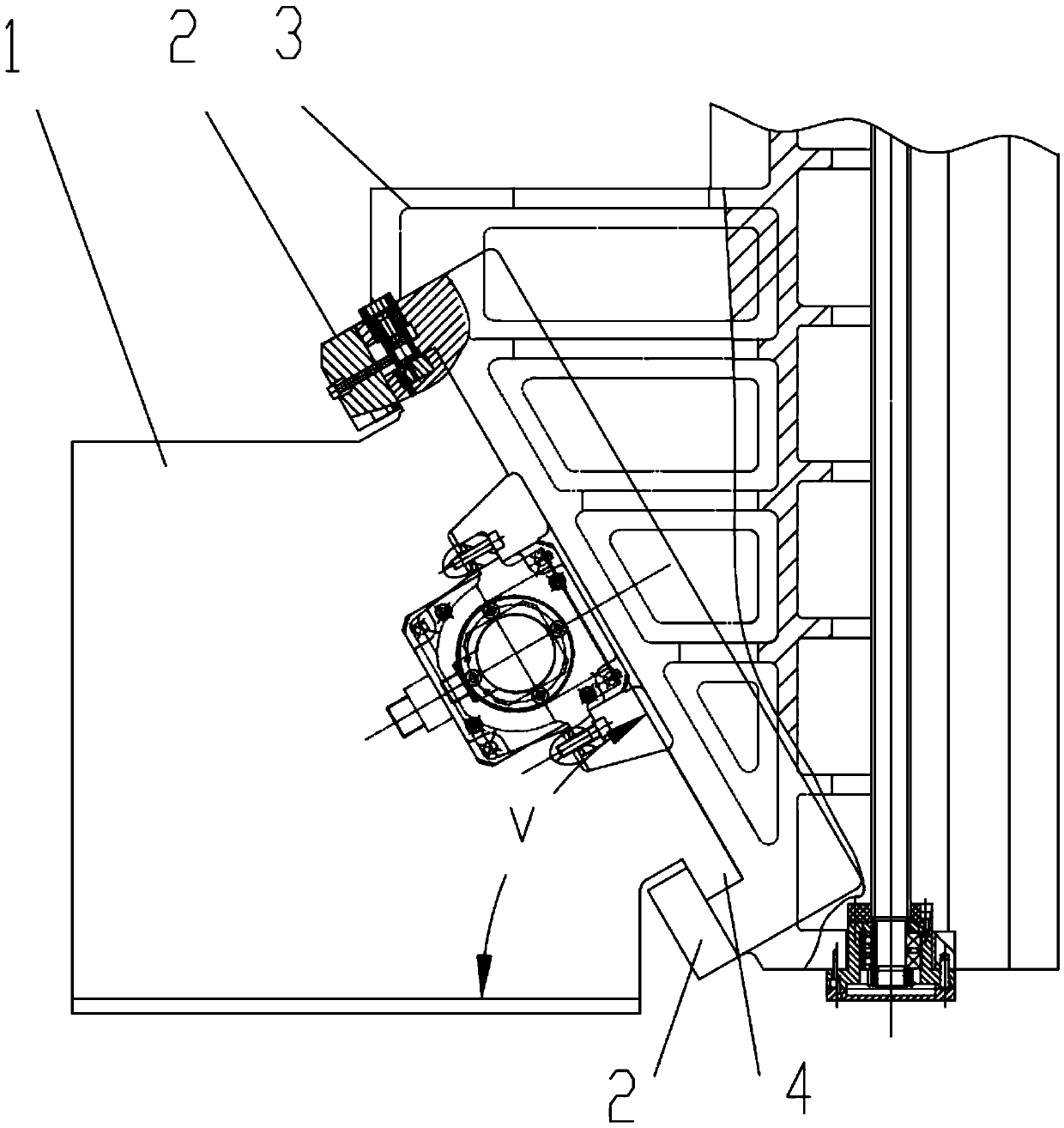
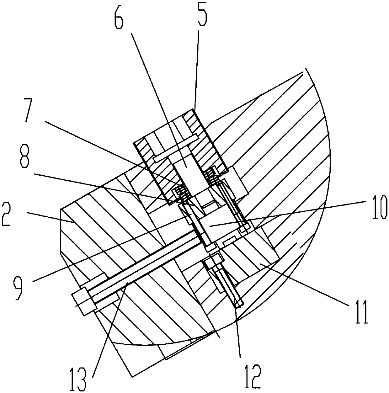
[0021] Embodiments of the present invention, such as figure 1 , figure 2 As shown, the inclined beam unloading composite guideway structure includes the beam, the slide seat 3 in the headstock, the rolling guide pair and the slide guide pair arranged between the beam and the slide seat 3 in the headstock, and the unloading adjustment device; The sliding seat 3 is guided and connected with the beam through the rolling guide rail pair and the sliding guide rail pair; The connecting side of the connecting side is provided with a cuboid-shaped notch that is recessed obliquely downward and matched with the inclined-plane block 4, and the rolling guide rail pair is arranged between the upper end surface of the inclined-plane block 4 and the upper top surface of the notch; the sliding guide rail pair is arranged on the inclined-plane block 4 between the slope of the gap and the slope of the notch.

[0022] The supporting guide rail of the sliding guide rail pair is the convex side...


PUM


Abstract

The invention discloses a combined unloading guide rail structure with an inclined crossbeam. The combined unloading guide rail structure comprises the crossbeam, a spindle-box middle sliding base, a rolling guide rail pair, a sliding guide rail pair and an unloading adjusting device, wherein the rolling guide rail pair and the sliding guide rail pair are arranged between the crossbeam and the spindle-box middle sliding base; the spindle-box middle sliding base is connected with the crossbeam in a guiding mode through the rolling guide rail pair and the sliding guide rail pair; the crossbeam is the inclined crossbeam, one side face of the inclined crossbeam is a slope facing upwards, a protruding cuboid-shaped slope block is arranged on the slope, the connection side face of the spindle-box middle sliding base is provided with a cuboid-shaped notch which is concave obliquely downwards and matched with the slope block, and the rolling guide rail pair is arranged between the upper end face of the slope block and the top face of the notch; the sliding guide rail pair is arranged between the slope of the slope block and the slope of the notch. The combined unloading guide rail structure is optimized, the unloading adjusting device cannot affect the degree of parallelism of guide rails in a redistribution process of adjusting force, and only by arranging the simple and reliable fine adjusting structure, the whole combined guide rails are large in bearing capacity, more uniform in stress, more stable in moving and ideal in using effect.

Description

technical field [0001] The invention belongs to the technical field of machine tools, and relates to a guide rail structure of a machine tool, in particular to an inclined beam unloading composite guide rail structure of a machine tool. Background technique [0002] The guide rail structure of the machine tool can be classified into three types based on the frictional contact mode of the guide rail pair, and can be divided into three types: sliding guide rail, rolling guide rail and static pressure guide rail; the sliding guide rail structure has the advantages of large bearing capacity and high rigidity, but the starting friction Easy to crawl. The rolling guide rail structure has the advantages of good motion sensitivity, high positioning, small friction coefficient, less prone to crawling, and good wear resistance, but the structure is more complicated and the vibration resistance is poor. The hydrostatic guideway has the advantages of small friction coefficient and smoo...

Claims


Application Information

Patent Timeline
Patent Type & Authority Patents(China)
IPC IPC(8): B23Q1/01B23Q11/00
CPCB23Q1/017B23Q11/00
Inventor 刘文志严积淼林金笔
Owner 福建省三机机床有限责任公司
Why Eureka
Try Eureka