A bent outlet high-voltage shielded electrical connector plug

An electrical connector, high-voltage technology, applied in the direction of connection, the device for reducing the stress at the connection of the wire, the parts of the connection device, etc. The effect of reducing the volume, improving the connection reliability, and ensuring the position degree

Active Publication Date: 2015-11-11
ZHEJIANG YONGGUI ELECTRIC EQUIP
View PDF5 Cites 0 Cited by
  • Summary
  • Abstract
  • Description
  • Claims
  • Application Information

AI Technical Summary

Problems solved by technology

[0003] The traditional bent outlet electrical connector plug generally adds an elbow at the end of the plug to achieve the purpose of the bent outlet. Only suitable for plugs with small currents, because plugs with large currents need to use cables with larger cross-sectional areas, and cables with large cross-sectional areas have a larger turning radius. For the plug of the current curved outlet, generally a terminal is connected to the wire first, and then connected to the contact through the terminal to achieve the curved outlet. In this solution, the shell needs to be made into a component, that is, a part cannot be bent. However, after the shell is made into components, the protection level is difficult to meet the standard; it can be seen that the traditional bent outlet plug cannot meet the requirements of modern industrial electrical systems, especially the use requirements of new energy vehicles for the bent outlet electrical connection plug

Method used


Image

  • A bent outlet high-voltage shielded electrical connector plug
  • A bent outlet high-voltage shielded electrical connector plug
  • A bent outlet high-voltage shielded electrical connector plug

Examples


Embodiment Construction

[0024] The present invention will be further described below with reference to the drawings and embodiments.

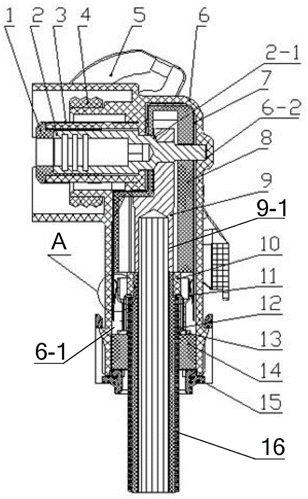
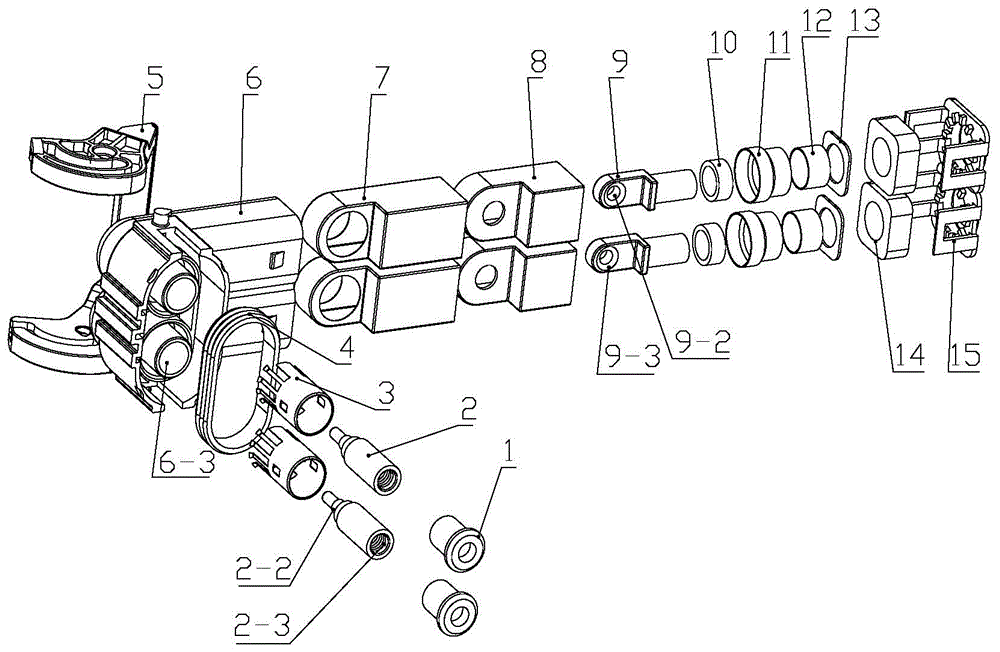
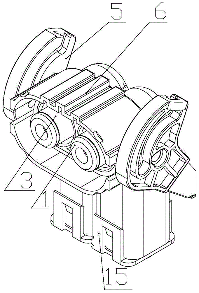
[0025] Such as figure 1 , 2 As shown in and 3, a bent-out high-voltage shielded electrical connector plug includes a plug housing 6, an adapter assembly, a wire assembly and a plug-in assembly. The plug housing 6 includes an integrally formed outlet part and a plug-in part. The outlet part and the plug-in part are arranged through the inside; the outlet part is provided with two adapter shielding installation grooves 6-1; the top of the plug-in part is provided with a sealing ring 4 , The outer wall is provided with a locking handle 5, and the inside is provided with two pin positioning holes 6-2 and two plug shield assembly holes 6-3, the pin positioning hole 6-2 and the corresponding plug shield assembly hole 6 -3 Coaxial arrangement; the insertion shield assembly hole 6-3 and the adapter shield installation slot 6-1 are arranged in mutually perpendicular planes. Each...


PUM


Abstract

The invention discloses a bend-type outgoing line high-voltage shielding electric connector plug. The protection grade of an outer shell of a traditional large current bend-type outgoing line plug hardly reaches the standard. An outer shell of the plug of the invention comprises an outgoing line part and a plugging part. A switchover shield is sleeved and arranged in each switchover shield installation groove of the outgoing line part. A switchover sheath is sleeved and arranged in each switchover shield. A wiring terminal is sleeved and arranged in each switchover sheath. Each switchover shield is in contact with a shield outer sleeve through a spring on the inner wall of the switchover shield. A shield inner sleeve is sleeved and arranged in each shield outer sleeve. A plugging shield is fixedly sleeved and arranged in each plugging shield assembling hole of the plugging part. A plugging column is sleeved and arranged in each plugging shield. The head part of each plugging column extends into a corresponding plugging column positioning hole of the outer shell of the plug. Screw threads of each plugging column are connected with a screw thread hole of the corresponding wiring terminal, and a conical surface of each plugging column is connected with a conical hole of the corresponding wiring terminal. According to the invention, the small-size internal bend-type outgoing line can be realized and the short circuit between lead wires and cable shielding layers can be prevented.

Description

Technical field [0001] The invention belongs to the field of electrical systems, and relates to electrical connectors, in particular to a bent-out high-voltage shielded electrical connector plug. Background technique [0002] In modern industrial electrical systems, electrical connectors are used more and more widely, and the number is increasing. The demand for connector outlet methods is also increasing, and the demand for 90° curved outlet is the majority. [0003] The traditional elbow outlet electrical connector plug generally adds an elbow at the end of the plug to achieve the purpose of elbow outlet. The elbow is connected with the plug shell in a threaded or snap-fit ​​manner. The elbow outlet plug of this scheme is adopted. It is only suitable for low-current plugs, because large-current plugs need to use cables with a larger cross-sectional area, and cables with large cross-sectional areas also have a larger turning radius. The solution of adding an elbow at the end of th...

Claims


Application Information

Patent Timeline
Patent Type & Authority Patents(China)
IPC IPC(8): H01R13/02H01R13/502H01R13/58H01R13/447H01R13/648H01R4/56
Inventor 范纪军范正军李统刚
Owner ZHEJIANG YONGGUI ELECTRIC EQUIP
Why Eureka
Try Eureka