Controlled kite and flying method thereof

A kite and pilot technology, applied in the field of unpowered manned aircraft, can solve the problems of not flying the kite, staying in the test, unable to actively control the kite, etc., to reduce the induced resistance and improve the rolling stability.

Inactive Publication Date: 2014-05-14
周振文
View PDF8 Cites 2 Cited by
  • Summary
  • Abstract
  • Description
  • Claims
  • Application Information

AI Technical Summary

Problems solved by technology

Up to now, there is no kite manned sports generally carried out. The personnel stay in the experimental stage with the help of kite flying, and there is no action of driving the kite. The kite is completely

Method used


Image

  • Controlled kite and flying method thereof
  • Controlled kite and flying method thereof
  • Controlled kite and flying method thereof

Examples


Embodiment 1

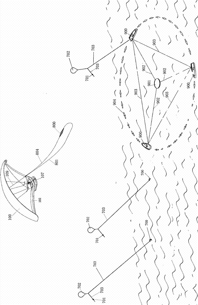
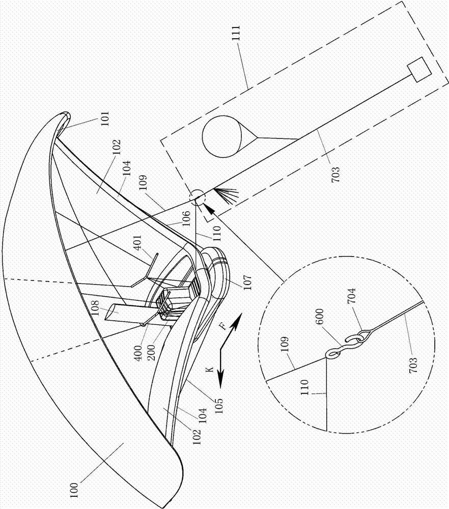
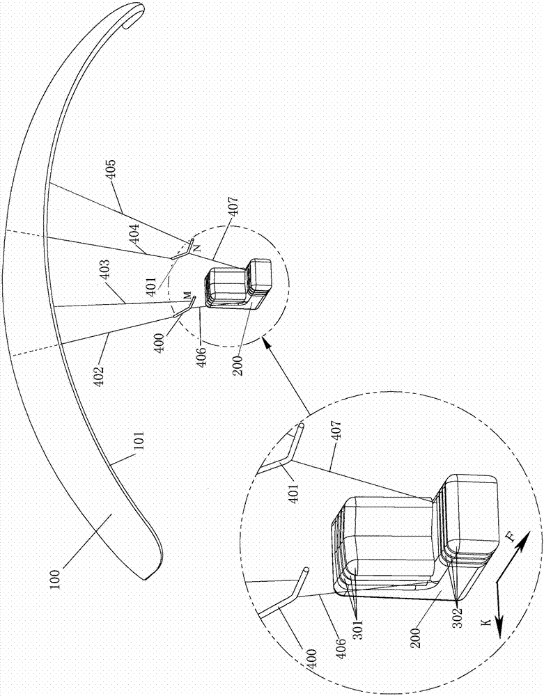
[0024] Embodiment 1, as attached figure 1 ~ attached Figure 9 As shown, the imperial kite includes: lifting force surface 100, upper main airbag and its branch airbags 101, lower lifting force surface 102, lower main airbag and its branch airbags 104, right pull-down line 105, left pull-down line 106, lifeboat 107, inflatable protection column 108. Lifting line 109, lifting line 110, inflatable seat 200, center of gravity adjustment device (including airbag back cushion 301, airbag pier 302), steering beam steering device (including right steering beam 400, left steering beam 401, right rear end cable 402, right front cable 403, left rear cable 404, left front cable 405, right middle cable 406, left middle cable 407) or acceleration cable deceleration cable driving device (including right acceleration cable 500, right deceleration cable 501, left Acceleration pull line 502, left deceleration pull line 503, left back upper connection line 504, left horizontal connection line ...

Embodiment 2

[0030] Embodiment 2, as attached Figure 4 , attached Figure 5As shown, the acceleration and deceleration cable driving device includes: left rear upper connection 118, left horizontal connection 119, left rear oblique connection 120, left middle rear connection 121, left front oblique connection 122, left middle front connection 123 124, the left acceleration cable 124, the left deceleration cable 125, the right rear upper connection 126, the right horizontal connection 127, the right rear oblique connection 128, the right middle rear connection 129, the right front oblique connection 130, the right middle front connection 131 , the right acceleration backguy 132, the right deceleration backguy 133; The connection line 121 is connected to a point B, the upper end of the left acceleration pull line 124 is connected to the left side of the front edge of the lift surface 100, and its lower end is connected to a point with the left horizontal connection line 119, the left middl...

Embodiment 3

[0031] Embodiment 3, as attached Figure 7 Figure 8 As shown, the umbrella anchor pulling line device includes umbrella anchor 800, umbrella anchor pulling line 801, steering double pulley 802, umbrella anchor recovery line 804, umbrella anchor line fixing hole 805, umbrella anchor line reel 806, handle 807, umbrella anchor The lower end of the pulling line 801 is connected to the umbrella anchor 800, and is anchored on the sea surface through the umbrella anchor 800. The steering double pulley 802 is suspended in the hook 600 at the lower end of the upper lifting line 109, and the upper lifting line 109 and the hanging hook 600 pull the umbrella anchor to the ground. The traction force of 801 is transferred to the middle part of the leading edge of the lift surface 100, the upper ends of the umbrella anchor recovery line 804 and the umbrella anchor traction line 801 are fixed in the umbrella anchor line fixing hole 805 provided by the umbrella anchor line reel 806, and the u...


PUM


Abstract

The invention relates to an unpowered manned craft, discloses a kite in which a kite pilot can ride, short for a controlled kite, and simultaneously discloses a flying method of the controlled kite. The controlled kite consists of an upper lifting surface and a lower lifting surface, wherein the lower lifting surface adopts a manner of an arc-shaped curved surface with a depressed middle part and two upwarping ends, and is distributed bisymmetrically, the wingtip parts of two ends of the upper lifting surface and the lower lifting surface are closely overlapped or connected with each other, a lifeboat, an inflatable seat, a gravity center regulating device, an inflation protection column and a driven beam driving device are arranged below the middle part of the lower lifting surface, the lower end of an upper hoisting line is connected with a traction line system through a lifting hook, the traction system has the following three modes: an iron anchor traction line device, an umbrella anchor traction line device, and an unmanned ship traction line device, and can be randomly switched to be in a traction state or a gliding state. The invention aims at creating a new sports item, and the manned kite can freely glide and distantly fly. The controlled kite has the advantages that the ground control on the kite is changed to air control, so that the ancient kite sports are more colorful.

Description

technical field [0001] The invention relates to an unpowered manned aircraft, which has the obvious characteristics of a kite. Background technique [0002] Many people at all times and in all over the world have carried out the research and exploration of manned kites flying to the sky. According to ancient records, the inventor of the kite, Gongshu Pan, "tasted it as a wooden kite and used it to see the city of Song Dynasty" more than 2,500 years ago. In 1894, Baden Powell was using The first European who succeeded in manned kite flight. In the summer of 2003, kite enthusiasts in Weifang conducted a relatively complete kite load test. In the case of a wind force of level 3 and a half, a 70-meter-long kite was used to carry a 45-kilogram kite. The load is raised by more than 20 meters. In 2010, Guangdong Chen Wangsong used a string kite to send a person weighing 60 kilograms into the sky. Up to now, there is no kite manned sports generally carried out. The personnel stay i...

Claims


Application Information

Patent Timeline
IPC IPC(8): B64C31/06
Inventor 不公告发明人
Owner 周振文
Why Eureka
Try Eureka