
Electric hydraulic filter throttling valve

A throttle valve and hydraulic technology, applied in the field of hydraulic throttle valve, can solve the problems of easy contamination of liquid, low adjustment accuracy, damaged hydraulic components, etc., achieve accurate flow, simple disassembly, and prevent damage from multiple openings Effect

Inactive Publication Date: 2014-05-14
NANTONG AMC MACHINERY
View PDF5 Cites 3 Cited by
  • Summary
  • Abstract
  • Description
  • Claims
  • Application Information

AI Technical Summary

Problems solved by technology

[0003] Chinese patent ZL201010589043.X discloses a throttle valve, which includes a valve body, a valve core and a regulating rod, the valve core is arranged in the valve body, and the outer diameter of the upper end of the valve body is larger than that of the part below the head. Outer diameter, the part below the head of the valve body is provided with external thread, the valve wall of the part below the head of the valve body is provided with more than one transverse channel, the valve body runs through up and down, and the lower end of the adjustment rod tops Hold one end of the spool, and the free end of the spool points to the opening at the lower part of the valve body. This patent can function as a general throttle valve, and at the same time connect hydraulic parts and pipelines, which can be used as a hinge bolt However, the patent is manually adjusted, so the adjustment is troublesome and the adjustment accuracy is not high. In addition, because the liquid in the hydraulic valve is easily polluted, it is easy to cause damage to the hydraulic components and cause a large error, which makes the adjustment low precision

Method used


Image

  • Electric hydraulic filter throttling valve

Examples


Embodiment

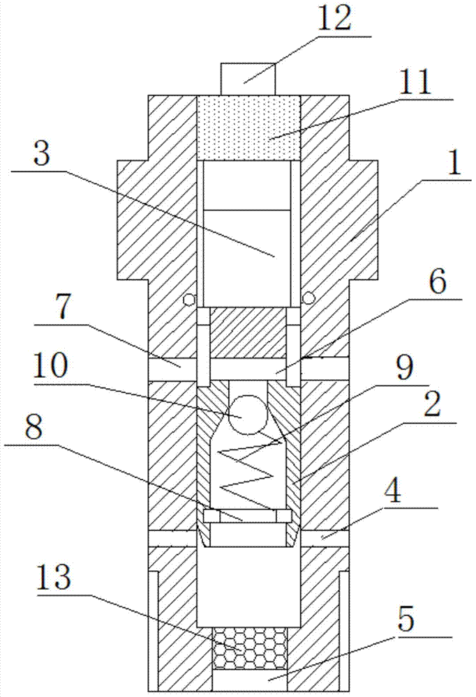
[0015] An electro-hydraulic filter throttle valve in this embodiment, such as figure 1 As shown, it includes a valve body, a valve core and an adjusting rod. The valve core is arranged in the valve body. The outer diameter of the upper end of the valve body is greater than the outer diameter of the part below the head. Some parts are provided with external threads, and more than one transverse channel is provided on the valve wall below the head of the valve body. The transverse channel is a liquid outlet channel. The valve body runs through up and down. One end of the core, the free end of the valve core points to the liquid inlet channel at the opening of the lower part of the valve body, and also includes a filter, a rotary motor and a screw propeller, the rotary motor and the screw propeller are connected in transmission, and the screw propeller The propeller is set in the valve body, and the actuating rod of the screw propeller is fixedly connected with the adjusting rod;...


PUM


Abstract

The invention relates to an electric hydraulic filter throttling valve, and belongs to the technical field of hydraulic throttling valves. The electric hydraulic filter throttling valve comprises a valve body, a valve core and an adjusting rod, wherein the valve core is arranged in the valve body, and one or more transverse channel is formed in the valve wall of part below the head of the valve body and is a liquid outlet channel. The electric hydraulic filter throttling valve further comprises a filter, a rotation motor and a spiral propeller, wherein the rotation motor is in transmission connection with the spiral propeller, the spiral propeller is arranged in the valve body, an actuating rod of the spiral propeller is fixedly connected with the adjusting rod, the filter is provided with a filter outer thread, the liquid inlet channel is provided with a filter inner thread matched with the filter outer thread, and the filter is connected to the valve body through the filter outer thread and the filter inner thread. According to the electric hydraulic filter throttling valve, liquid flow can be adjusted easily, adjustment accuracy is high, liquid can be filtered, and the valve core is prevented from being damaged.

Description

technical field [0001] The invention relates to an electrohydraulic filter throttle valve, which belongs to the technical field of hydraulic throttle valves. Background technique [0002] At present, the existing throttle valve includes a valve body, a valve core and a regulating rod, and the position of the valve core is adjusted by the regulating rod, thereby changing the liquid flow. [0003] Chinese patent ZL201010589043.X discloses a throttle valve, which includes a valve body, a valve core and a regulating rod, the valve core is arranged in the valve body, and the outer diameter of the upper end of the valve body is larger than that of the part below the head. Outer diameter, the part below the head of the valve body is provided with external thread, the valve wall of the part below the head of the valve body is provided with more than one transverse channel, the valve body runs through up and down, and the lower end of the adjustment rod tops Hold one end of the spoo...

Claims


Application Information

Patent Timeline
Patent Type & Authority Applications(China)
IPC IPC(8): F15B13/02F15B21/04F16K31/04
Inventor 戚顺平
Owner NANTONG AMC MACHINERY
Learn More