Finned tube heat exchanger

A heat exchanger and finned tube technology, applied in the field of finned tube heat exchangers, can solve problems such as fin frosting, and achieve the effect of suppressing the decline of heat exchange performance

Active Publication Date: 2017-07-04
PANASONIC CORP
View PDF1 Cites 0 Cited by
  • Summary
  • Abstract
  • Description
  • Claims
  • Application Information

AI Technical Summary

Problems solved by technology

[0007] In the case where the above-mentioned conventional finned tube heat exchanger is used, for example, in an outdoor unit of an air conditioner, especially during heating operation when the outside air temperature is low, condensation is likely to occur on the windward side of the fins 111. Frost

Method used


Image

  • Finned tube heat exchanger
  • Finned tube heat exchanger
  • Finned tube heat exchanger

Examples


no. 1 Embodiment approach )

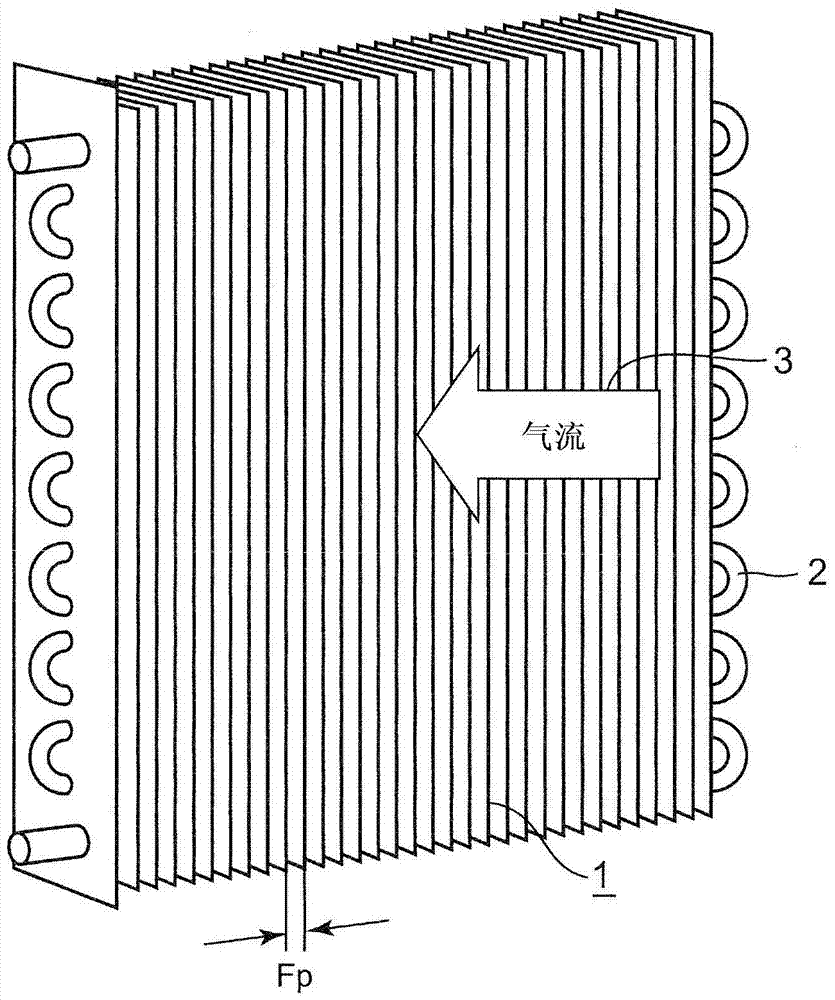
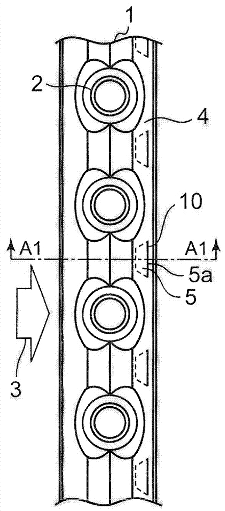
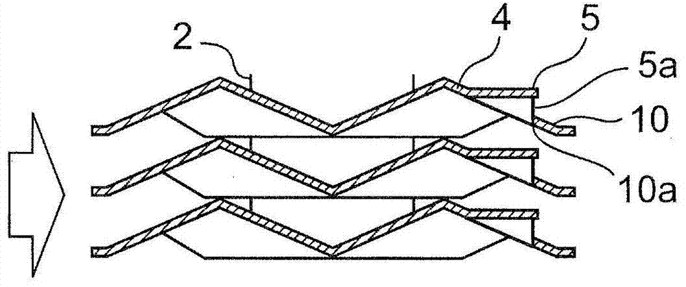
[0053] figure 1 It is a perspective view of the finned tube heat exchanger of 1st Embodiment of this invention. Figure 2A Yes figure 1 A partial plan view of fins included in the shown finned tube heat exchanger. Figure 2B Yes Figure 2A A1-A1 line sectional drawing. Figure 2C is in Figure 2A An explanatory diagram showing the flow of the airflow in the A1-A1 line sectional view. The finned tube heat exchanger according to the first embodiment is installed, for example, in outdoor units such as air conditioners, heat pump water heaters, and heat pump hot water heaters.

[0054] like figure 1 As shown, the finned tube heat exchanger according to the first embodiment includes: a plurality of fins 1 stacked at a distance Fp to form a flow path of the air flow 3; A heat transfer tube 2.

[0055] A fluid flows through the inside of the heat transfer tube 2 , and the fluid exchanges heat with an air flow 3 such as air sent between the plurality of fins 1 by a blower (...

no. 2 approach )

[0064] Below, refer to Figure 4A ~ Figure 4C , the finned tube heat exchanger according to the second embodiment of the present invention will be described.

[0065] Figure 4A It is a partial plan view of the fins included in the fin-tube heat exchanger according to the second embodiment. Figure 4B is in Figure 4A An explanatory diagram showing the stagnant state of the condensed water in the sectional view of line A2-A2 of . Figure 4C is in Figure 4A An explanatory diagram showing the drainage of condensate in the enlarged plan view of .

[0066] The finned tube heat exchanger of the second embodiment differs from the finned tube heat exchanger of the first embodiment described above in that Figure 4C As shown, there is an upright piece 8a, and the upright piece 8a connects the upright surface 5b formed at the lower end portion in the vertical direction of the one-side upturned notch portion 5 and the rear edge portion (the end on the leeward side) of the fin 1 P...

no. 3 Embodiment approach )

[0072] Below, refer to Figure 5A ~ Figure 5C , a finned tube heat exchanger according to a third embodiment of the present invention will be described.

[0073] Figure 5A It is a partial plan view of the fins included in the fin-tube heat exchanger according to the third embodiment of the present invention. Figure 5B Yes Figure 5A A3-A3 Line Sectional Drawing. Figure 5C is in Figure 5A An explanatory diagram showing the flow direction of the airflow in the A3-A3 line cross-sectional view.

[0074] The finned tube heat exchanger of the third embodiment differs from the finned tube heat exchanger of the second embodiment described above in that Figure 5B or Figure 5C As shown, the strip-shaped fin portion 10 located on the leeward side of the single-turned notch 5 is parallel to the main surface 5 c extending in the vertical direction of the single-turned notch 5 .

[0075] According to the third embodiment, the strip-shaped fin portion 10 is parallel to the main ...


PUM


Abstract

The invention provides a finned tube heat exchanger that prevents the heat exchange performance from declining caused by frosting and condensed water. The finned tube heat exchanger comprises multiple fins (1) laminated in a mutually spaced manner, and multiple heat transfer tubes (2) penetrating the multiple fins (1) in the lamination direction. Fluids for heat exchange of air flows flowing across the multiple fins (1) communicate with the inside of the multiple heat transfer tubes (2). Each fin (1) has an inclined surface (4), in at least more than one position, enabling the flowing direction of the air flows to be bent. One inclined surface positioned at the outmost leeward side among the inclined surfaces is equipped with a single side turning cutting portion (5) in a cutting and molding way that only the leeward side has an opening port (5a).

Description

technical field [0001] The present invention relates to a finned tube heat exchanger for heat exchange of refrigerant. Background technique [0002] In the prior art, such finned tube heat exchangers as Figure 7 What is shown includes: a plurality of fins 101 stacked at intervals from each other; and a plurality of heat transfer tubes 102 provided to pass through the plurality of fins 101 in the stacking direction. [0003] In this finned tube heat exchanger, an airflow 103 such as air sent by a blower (not shown) flows between the fins 101 adjacent to each other, thereby interacting with the fluid flowing through the inside of the heat transfer tube 102 Perform heat exchange. [0004] As a finned tube heat exchanger having such a structure, it is disclosed, for example, in Patent Document 1 (Japanese Patent Laid-Open No. 2001-091101). [0005] Figure 8A It is a partial plan view of the fins included in the conventional fin-tube heat exchanger. Figure 8B Yes Figure ...

Claims


Application Information

Patent Timeline
Patent Type & Authority Patents(China)
IPC IPC(8): F25B39/00F28F1/32F28F13/02
Inventor 名越健二横山昭一野间富之木田琢己朔晦诚广田正宣山本宪昭
Owner PANASONIC CORP
Why Eureka
Try Eureka