
Heat exchanger and heat exchange method

A heat exchanger and heat exchange tube technology, applied in the direction of heat exchanger shell, indirect heat exchanger, heat exchange equipment, etc., can solve the problems of excessive load, large-scale installation cost, etc. Effect of decrease in exchange performance

Active Publication Date: 2015-02-04
MITSUBISHI ELECTRIC CORP
View PDF5 Cites 1 Cited by
  • Summary
  • Abstract
  • Description
  • Claims
  • Application Information

AI Technical Summary

Problems solved by technology

However, bending the header into an L-shape or a U-shape, for example, imposes an excessive load, resulting in an increase in device size and cost.

Method used


Image

  • Heat exchanger and heat exchange method
  • Heat exchanger and heat exchange method
  • Heat exchanger and heat exchange method

Examples


Embodiment approach 1

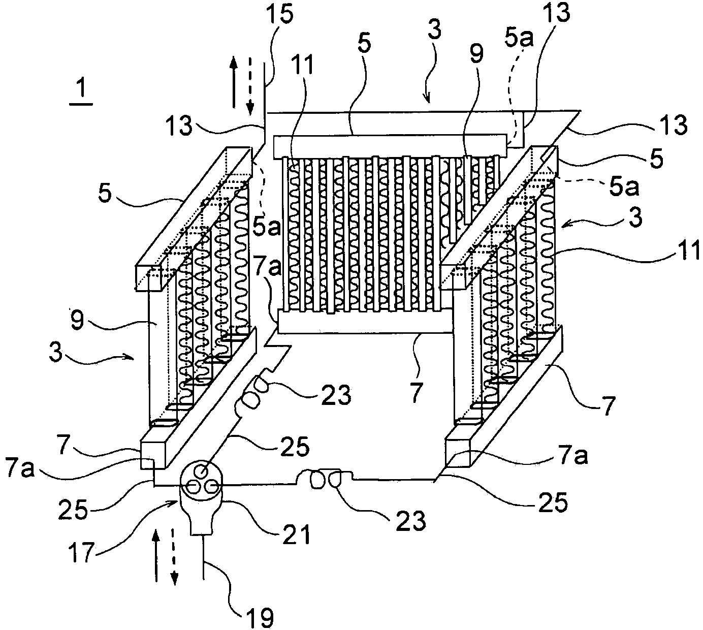
[0027] figure 1 It is a figure which shows the structure of the heat exchanger of this Embodiment 1. The heat exchanger of this embodiment functions as an outdoor unit of an air conditioner that is installed in a target space and performs cooling and heating. Therefore, it is a parallel flow heat exchanger in which the refrigerant such as figure 1 As indicated by the dotted arrow in , the refrigerant flows from top to bottom. When heating, the refrigerant acts as an evaporator, such as figure 1 Flow from bottom to top as indicated by the solid arrows in .

[0028] The heat exchanger 1 has a plurality of heat exchange functional surfaces 3 . also, figure 1 An example of the case where there are three heat exchange functional surfaces 3 is shown. In addition, in figure 1 In the example of , adjacent heat exchange functional surfaces 3 are configured to point in orthogonal directions.

[0029] On each heat exchange functional surface 3, an upper header 5, a lower header 7,...

Embodiment approach 2

[0048] based on Figure 6 Embodiment 2 of the present invention will be described. In Embodiment 1 above, it was exemplified that the dryness of the refrigerant is adjusted uniformly on a plurality of heat exchange functional surfaces, and that the degree of dryness of the refrigerant is adjusted accordingly to the different heat loads on each heat exchange functional surface (mainly depends on the passing wind speed of the heat exchange unit). The manner of changing the refrigerant flow rate, but the present invention is not limited thereto. That is, the present invention also includes ways to adjust the dryness of the refrigerant and / or the flow rate of the refrigerant to be different on multiple heat exchange functional surfaces. As a specific example of application, an example of application to an outdoor unit of a box-type air conditioner can be mentioned. Figure 6 It is a diagram showing the appearance and plan of the outdoor unit of the box-type air conditioner.

[...


PUM


Abstract

A heat exchanger (1) has a plurality of heat exchange functional surfaces, is capable of suppressing the effect of gravity on a refrigerant, and suppresses decreases in the heat exchange performance at each surface. The heat exchanger has the plurality of heat exchange functional surfaces (3) and, in each heat exchange functional surface, upper header pipes (5), lower header pipes (7), and a plurality of heat exchange pipes (9) provided between each pair of upper and lower header pipes. The plurality of heat exchange functional surfaces are in a parallel-connected relationship and the plurality of lower header pipes are connected to a lower collector pipe (19) via a branch flow adjustment unit (17).

Description

technical field [0001] The invention relates to a heat exchanger and a heat exchanging method. Background technique [0002] As one form of the heat exchanger, there is a parallel flow heat exchanger. This heat exchanger includes a pair of headers and a plurality of flat tubes provided between the headers, and a fluid flowing into one header flows out to the other header after passing through the plurality of flat tubes. [0003] In this parallel flow heat exchanger, when the pair of header pipes are arranged in the vertical direction, the liquid refrigerant in the gas-liquid two-phase refrigerant tends to flow toward the relatively lower flat tube due to the influence of gravity. , it is difficult to evenly distribute the refrigerant to the plurality of flat tubes. [0004] Therefore, in the structure of the side-flow heat exchanger, there is also an aspect in which a pair of headers are arranged horizontally, and the interaction between the plurality of flat tubes is les...

Claims


Application Information

Patent Timeline
Patent Type & Authority Applications(China)
IPC IPC(8): F28F9/26
CPCF28D1/0417F28D1/05366F25B2400/121F24F1/16F28D2021/0068F28D1/0426F28F9/26F25B39/028F28F9/0273F28D7/16
Inventor 冈崎多佳志石桥晃李相武松田拓也
Owner MITSUBISHI ELECTRIC CORP
Learn More