Heat exchange plate for plate heat exchanger and plate heat exchanger with same

A technology of plate heat exchanger and heat exchange plate, which is applied in the direction of heat exchange equipment, lighting and heating equipment, laminated components, etc., can solve the problems of low strength and stress concentration of heat exchangers, increase the welding area, increase Strength, effect of promoting lateral fluid distribution

Active Publication Date: 2014-05-14
DANFOSS MICRO CHANNEL HEAT EXCHANGER JIAXING
View PDF5 Cites 11 Cited by
  • Summary
  • Abstract
  • Description
  • Claims
  • Application Information

AI Technical Summary

Problems solved by technology

[0002] In the prior art, the heat exchange plate of the plate heat exchanger is narrow due to the narrow top of the slender ridge, and the structure of the solder joints will cause stress concentration, resulting in low strength of the heat exchanger

Method used


Image

  • Heat exchange plate for plate heat exchanger and plate heat exchanger with same
  • Heat exchange plate for plate heat exchanger and plate heat exchanger with same
  • Heat exchange plate for plate heat exchanger and plate heat exchanger with same

Examples


Embodiment 1

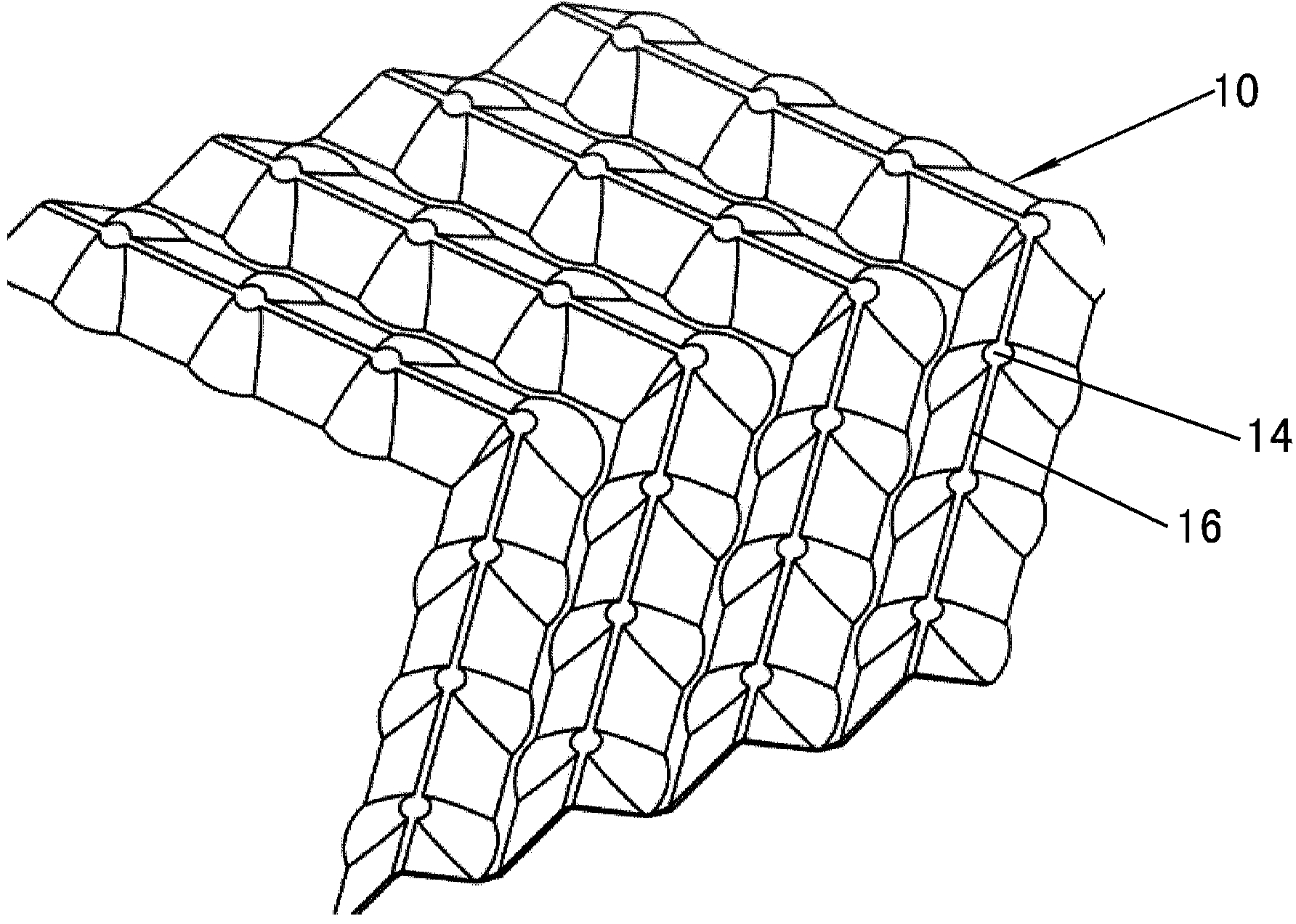
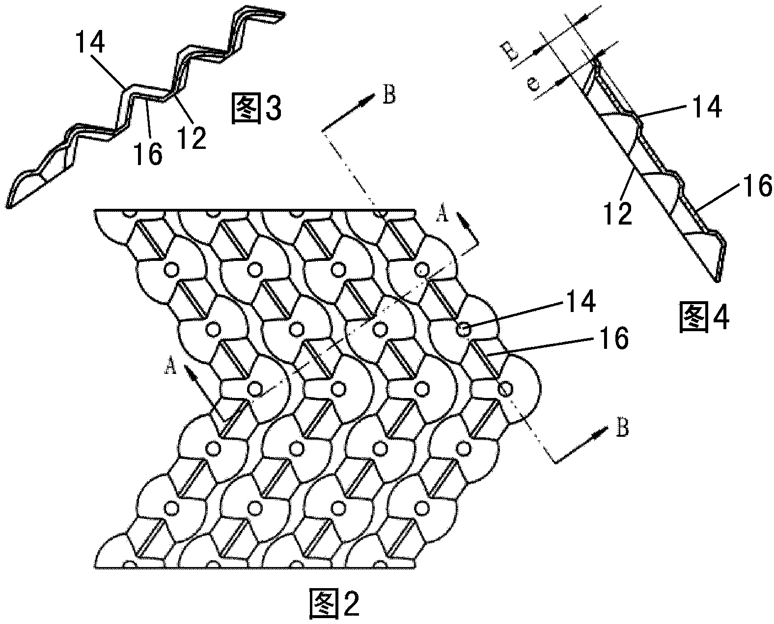
[0036] Such as Figures 1 to 4 As shown, the heat exchange plate for a plate heat exchanger according to an embodiment of the present invention includes a heat exchange portion 10 constituting a heat exchange portion of a fluid of the plate heat exchanger. The heat exchange plate also includes a plurality of protrusions 14 protruding from the plate plane 12 to one side of the plate plane 12 in the heat exchange part 10, the plurality of protrusions 14 are arranged along a plurality of lines, and a part of the plurality of protrusions 14 It can be used as a welding part or a receiving part where the heat exchange plate is welded or received with an adjacent heat exchange plate. The plurality of lines are generally arranged in a V-shape, W-shape or wave pattern or in other suitable pattern when viewed towards the plane of the panel. The plate plane 12 is the plane in which the heat exchange plate lies before it has been stamped.

[0037] Such as Figures 1 to 4 As shown, the ...

Embodiment 2

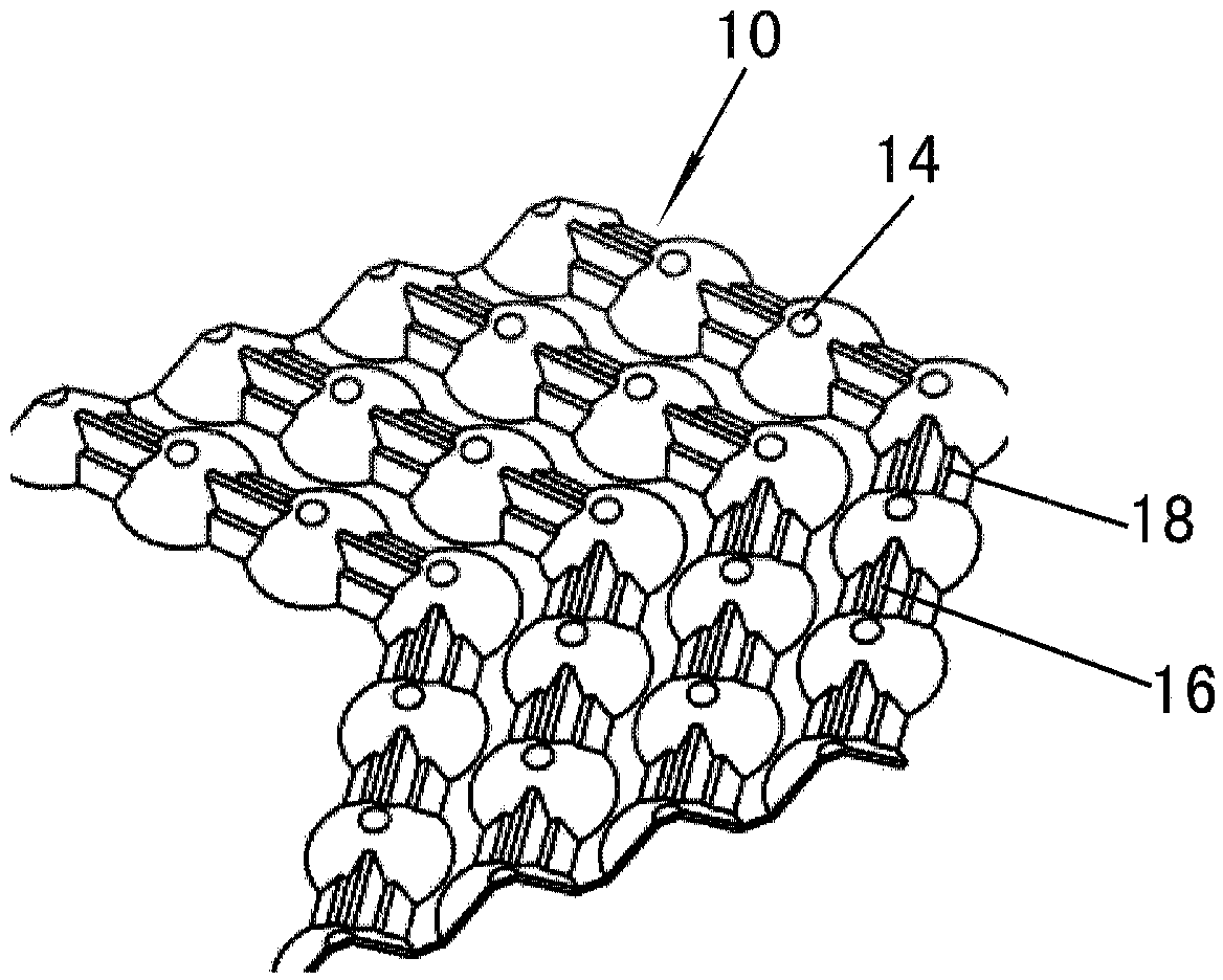
[0041] Embodiment 2 according to the present invention differs from the above embodiments in that the transition portion 16 is provided with a stepped portion.

[0042] Such as Figures 5 to 8 As shown, the transition 16 has a step 18 between the top of the transition 16 and the plate plane 12 when viewed in a direction perpendicular to the line. The steps 18 are arranged on both sides of the symmetry plane of the transition part 16, so that the cross-sectional shape of the transition part 16 is roughly "convex".

[0043] Such as Figure 7 As shown, the distance E of the top of the protrusion 14 from the plate plane 12 is greater than or equal to the distance e2 of the top of the transition portion 16 from the plate plane 12 . The distance e1 of the top of the step 18 from the plate plane 12 is smaller than the distance e2 of the top of the transition portion 16 from the plate plane 12 and the distance E of the top of the protrusion 14 from the plate plane 12 .

[0044] By ...

Embodiment 3

[0046] Embodiment 3 according to the present invention differs from Embodiment 2 above in that the top of the transition portion and the top of the protrusion 14 are substantially in the same plane.

[0047] Such as Figures 9 to 12As shown, the distance E of the top of the protrusion 14 from the plate plane 12 is equal to the distance e2 of the top of the transition portion 16 from the plate plane 12 . The distance e1 of the top of the step 18 from the plate plane 12 is smaller than the distance e2 of the top of the transition portion 16 from the plate plane 12 and the distance E of the top of the protrusion 14 from the plate plane 12 .


PUM


Abstract

The invention discloses a heat exchange plate for a plate heat exchanger. The heat exchange plate comprises a heat exchange part, a plurality of protrusions and transition parts. The protrusions protrude from a plate plane to at least one side of the plate plane on the heat exchange part, and are distributed along a plurality of lines. The transition parts are arranged between the adjacent protrusions distributed along one line and protrude towards the at least one side of the plate plane, and the dimension of the top of each protrusion in the direction perpendicular to the lines is larger than that of the tops of the transition parts. The dimension of a welding part or the dimension of a bearing part is increased, and therefore the strength of the heat exchange plate of the plate heat exchanger is improved.

Description

technical field [0001] The invention relates to a heat exchanger, in particular to a heat exchange plate for a plate heat exchanger and a plate heat exchanger with the heat exchange plate. Background technique [0002] In the prior art, the heat exchange plates of the plate heat exchanger have narrow tops due to the elongated ridges, and the solder joint structure will cause stress concentration, resulting in low strength of the heat exchanger. Contents of the invention [0003] An object of the present invention is to provide a heat exchange plate for a plate heat exchanger and a plate heat exchanger having the heat exchange plate, by increasing the size of the welding part or the receiving part, thereby improving The strength of the heat exchange plate. [0004] Another object of the present invention is to provide a heat exchange plate for a plate heat exchanger and a plate heat exchanger having the heat exchange plate, thereby increasing the strength of the heat excha...

Claims


Application Information

Patent Timeline
Patent Type & Authority Applications(China)
IPC IPC(8): F28F3/04
CPCF28F3/042F28F3/025
Inventor 魏文建张志锋李华马文勇
Owner DANFOSS MICRO CHANNEL HEAT EXCHANGER JIAXING
Why Eureka
Try Eureka