Tightening and fixing structure of test tank rear cover

A technology for fixing structures and test objects, applied in the direction of measuring devices, instruments, measuring electricity, etc.

Inactive Publication Date: 2014-05-14
JIANGSU QIYUAN LEIYU ELECTRICAL TECH
View PDF0 Cites 0 Cited by
  • Summary
  • Abstract
  • Description
  • Claims
  • Application Information

AI Technical Summary

Problems solved by technology

The workload of changing the test sample is large, time-consuming, labor-intensive, and the work efficiency is not high

Method used


Image

  • Tightening and fixing structure of test tank rear cover
  • Tightening and fixing structure of test tank rear cover
  • Tightening and fixing structure of test tank rear cover

Examples


Embodiment Construction

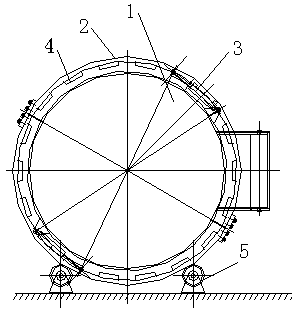
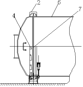
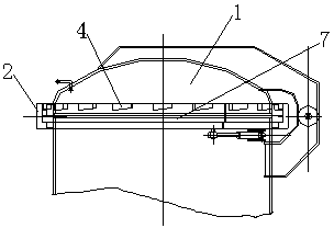
[0016] 18 oblique wedges 4 are evenly distributed on the circumference of the test tank rear cover 1 and the concave groove 2 of the present invention, and the oblique wedges 4 are entities with a certain inclination. Both oblique wedges 4 are symmetrically distributed, and the length of the vacant part is greater than the length of the oblique wedge 4 entities.

[0017] The rear cover 1 and the tank body 6 of the sample tank are fixed by a central axis 7, and the two central axes 7 form a line, which can be opened and closed freely. The concave groove 2 can rotate at a certain angle on the circumference, and the direction of rotation is realized by two hydraulic cylinders 3 on the tank body 6 . The bottom of the concave groove 2 is provided with a guiding device 5 to ensure that the concave groove 2 can rotate smoothly.

[0018] In the present invention, the rear cover 1 is manually closed at first, and the concave groove 2 is driven to rotate through the hydraulic cylinder ...


PUM


Abstract

The invention relates to a tightening and fixing structure of a test tank rear cover. The tightening and fixing structure comprises a rear cover and a tank body cooperating with the rear cover; a concave groove is arranged at the connection position of the rear cover and the tank body in a circumferential mode; and oblique wedges for fixing the rear cover are correspondingly arranged at the rear cover and the concave groove. And arrangement of a vacant portion of the rear cover meets the following condition: the oblique wedge at the concave groove is completely located at the vacant portion but is not contacted with the oblique wedge of the rear cover. According to the invention, the structure has the following advantages: (1), with application of the oblique wedge structure, objectives of screwing and loosening are achieved based on cooperation of the oblique wedges at the concave groove and the rear cove; and the friction force formed between the oblique wedges is large and the screwing is reliable; (2), the concave groove is driven by a hydraulic cylinder to make rotation, so that time and labor are saved and screwing is reliable; and (3), a concave groove rotation guiding device is further arranged and thus the concave groove can work stably, so that a defect that some oblique wedges bear large forces and thus are damaged or locked due to deflection of the concave groove during working can be overcome and thus the normal operation of the oblique wedges can be ensured.

Description

technical field [0001] The invention relates to a structure for tightening and fixing the back cover of a pilot tank body of a million volt pure gas type test transformer, specifically a structure that does not adopt the traditional tightening and fixing structure with bolts. Background technique [0002] With the rapid development of the national economy, my country's power industry has developed rapidly, and the voltage level has been increased from the previous 220kV and 500kV voltage levels to 1000kV voltage levels. The voltage level of the factory test equipment for electrical equipment has also been increased. This invention is related to GIS, medium and high voltage insulation basin test tank for combined electrical appliances. [0003] In the past, the voltage level and diameter of the test tank were not high or large (the voltage level was 800kV, and the diameter of the test tank body was less than 1 meter). Manual hoisting and bolt tightening were used. With the in...

Claims


Application Information

Patent Timeline
Patent Type & Authority Applications(China)
IPC IPC(8): G01R1/02G01R31/00
Inventor 张旗张生林傅正财王俭辛张礼刚刘晓珂
Owner JIANGSU QIYUAN LEIYU ELECTRICAL TECH
Why Eureka
Try Eureka