Modulated laser range finder and method

A technology of laser range finder and laser, which is applied in the direction of instruments, measuring devices, radio wave measuring systems, etc., and can solve problems such as limitations

Inactive Publication Date: 2014-05-14
THE BOEING CO
View PDF2 Cites 8 Cited by
  • Summary
  • Abstract
  • Description
  • Claims
  • Application Information

AI Technical Summary

Problems solved by technology

Therefore, the utilization of conventional "t

Method used


Image

  • Modulated laser range finder and method
  • Modulated laser range finder and method
  • Modulated laser range finder and method

Examples


Embodiment Construction

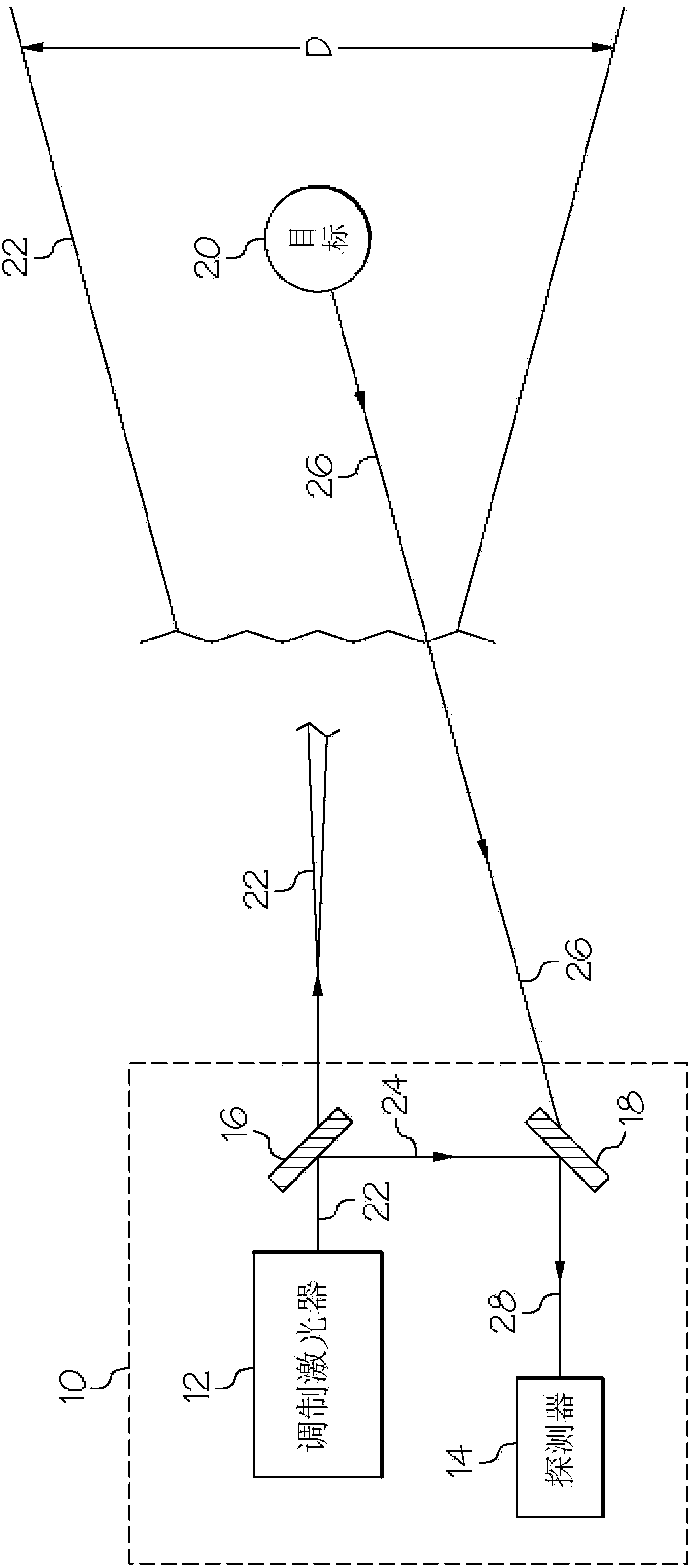
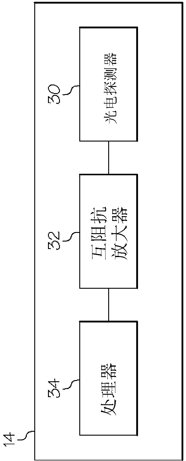
[0055] refer to figure 1 , one embodiment of the disclosed modulated laser rangefinder—generally designated 10—may include a laser 12 , a detector 14 , a first beam splitter 16 and a second beam splitter 18 . The modulated laser rangefinder 10 may be employed to measure the distance to the target object 20 and optionally measure the depth, acceleration, scatter cross-section and / or angular position of the target object 20 .

[0056]Laser 12 may project a continuous laser beam 22 toward a target object 20 . The diameter D of laser beam 22 at a given distance from laser 12 may be a function of beam divergence (eg, 1 degree), which will depend on the type of laser 12 chosen to modulate laser rangefinder 10 , etc. Accordingly, the field of view of the modulated laser range finder 10 may increase with distance from the modulated laser range finder 10 .

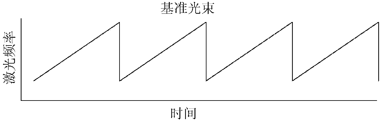
[0057] Laser 12 may continuously modulate the frequency of laser beam 22 at a known frequency modulation rate. Any available t...


PUM


Abstract

The invention provides a modulated laser range finder and method. The laser range finder including a laser configured to project a laser beam onto a target object thereby causing a target beam to be reflected from the target object, wherein the laser beam has a frequency, and wherein the frequency is modulated at a known rate, a first beam splitter positioned to split a reference beam from the laser beam, a second beam splitter positioned to receive the target beam and the reference beam, wherein the target beam and the reference beam are coherently combined, the coherently combined beams establishing a difference frequency, and a detector configured to measure the difference frequency.

Description

technical field [0001] This application relates to the measurement of the distance to a target object, and more particularly to the measurement of the distance to a target object using a frequency modulated laser beam. Background technique [0002] Laser range finders project a laser beam to measure the distance to a target object. Conventional laser rangefinders are relatively compact while still providing relatively accurate distance measurements. Accordingly, conventional laser rangefinders are used in a variety of applications, such as sports applications (eg, golf and hunting), construction applications (eg, surveying), and military applications (eg, target acquisition). [0003] Traditional laser rangefinders typically use a "time-of-flight" method to measure distance. A time-of-flight laser rangefinder generally includes a laser and a detector. The laser projects a laser pulse towards the target object and starts a clock. The detector detects the backscatter due t...

Claims


Application Information

Patent Timeline
IPC IPC(8): G01S17/32G01S17/34
CPCG01S7/493G01S17/34
Inventor D·R·琼沃思
Owner THE BOEING CO
Why Eureka
Try Eureka