
Controller and method for collision detection

A technology of controllers and receivers, applied in the field of controllers, can solve the problems of not having any reference, not knowing the frequency position of potential transponders, and being unable to receive transmission streams, etc.

Inactive Publication Date: 2014-05-14
SONY GRP CORP
View PDF0 Cites 0 Cited by
  • Summary
  • Abstract
  • Description
  • Claims
  • Application Information

AI Technical Summary

Problems solved by technology

In most of these scans, the transport streams are usually not received since the frequency positions of the potential transponders that comprise them are still not known
In the remaining part, it is possible to receive such a transport stream, but there is still no reference to decide whether the received transport stream corresponds to the frequency selected by the DiSEqC command

Method used


Image

  • Controller and method for collision detection
  • Controller and method for collision detection
  • Controller and method for collision detection

Examples


Embodiment Construction

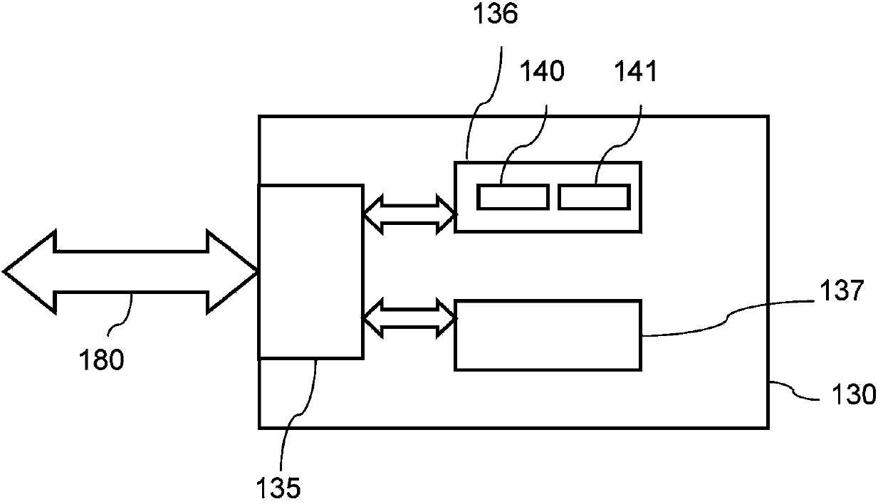
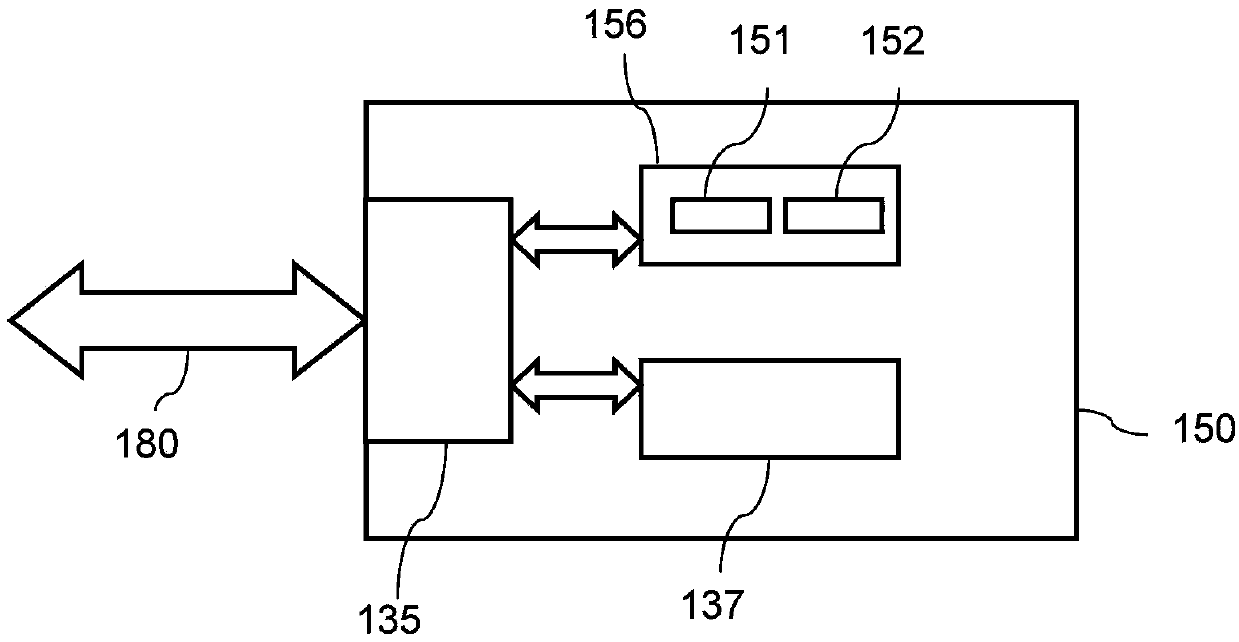
[0030] Referring now to the drawings, wherein like reference numerals designate like or corresponding parts throughout the several figures, Figure 1A One embodiment of a controller 130 is shown. The controller 130 includes a controller interface 135 connected to the bus 180 on the outside of the controller 130, which is connected to a system such as a satellite receiver system. The controller 130 further includes a sensor 136 having a voltage source 140 and a current sensor 141 connected to the controller interface 135 . The voltage source 140 is configured to apply a sense voltage to the bus 180 , and the current sensor 141 is configured to measure the sense current on the bus 180 . The controller 130 further comprises a transmitter 137 connected to a controller interface 135 adapted to transmit data on the bus 180 .

[0031] As long as the transmitter 137 is not sending a data signal to the bus 180 , the controller 130 applies the supply voltage to the bus 180 . In one em...


PUM


Abstract

The invention discloses a controller and a method for collision detection. The method for detecting a signal activity on a bus comprises measuring a current on the bus, and determining a signal activity based on the measured current.

Description

technical field [0001] The present disclosure relates to a controller and a method for detecting signal activity on a bus. Background technique [0002] In systems where several individual masters can be connected to one slave, such as a single cable satellite dish system, more than one master can initiate simultaneous data transmissions to the slaves. This can cause data collisions, resulting in data loss. In order to ensure that all sending units are functioning well, it is necessary to provide means to detect and avoid data collisions. [0003] In a single cable satellite dish system, several receivers are connected to a single cable interface (SCIF). Typically, up to 8 individual receivers can be connected to the SCIF. Each receiver can be tuned to a different frequency. A common standard is the use of the "Digital Satellite Equipment Control Bus" (DiSEqC) for communication between the receiver and the SCIF. [0004] According to the single cable standard (EN50494:2...

Claims


Application Information

Patent Timeline
Patent Type & Authority Applications(China)
IPC IPC(8): G06F13/38
CPCH04L12/413H04Q2213/13299G01R27/28G06F2101/00G06F2200/00G06F1/00
Inventor 本·艾特尔海莫·古特
Owner SONY GRP CORP
Learn More