Vehicle air bag system

a technology for air bags and vehicles, applied in the direction of pedestrian/occupant safety arrangements, roofs, tractors, etc., can solve the problems of poor air bag installation, poor visibility, and complex installation of air bag modules

Inactive Publication Date: 2002-11-05
NISSAN MOTOR CO LTD
View PDF18 Cites 70 Cited by
  • Summary
  • Abstract
  • Description
  • Claims
  • Application Information

AI Technical Summary

Problems solved by technology

It has been determined from the disclosure of from the former invention, in which the air bag module is stored inside the front pillar, has the following drawbacks: the air bag module installability is poor because the closed cross sectional area of the front pillar is limited, the structure becomes complex, and the front pillar becomes larger making visibility poor.
Consequently, the air bag module is large and its installability is poor.
Furthermore, such a structure is disadvantageous in terms of cost and the air bag cannot cover the entire front surface of the front pillar from the base part to the upper end part.

Method used


Image

  • Vehicle air bag system
  • Vehicle air bag system
  • Vehicle air bag system

Examples


third embodiment

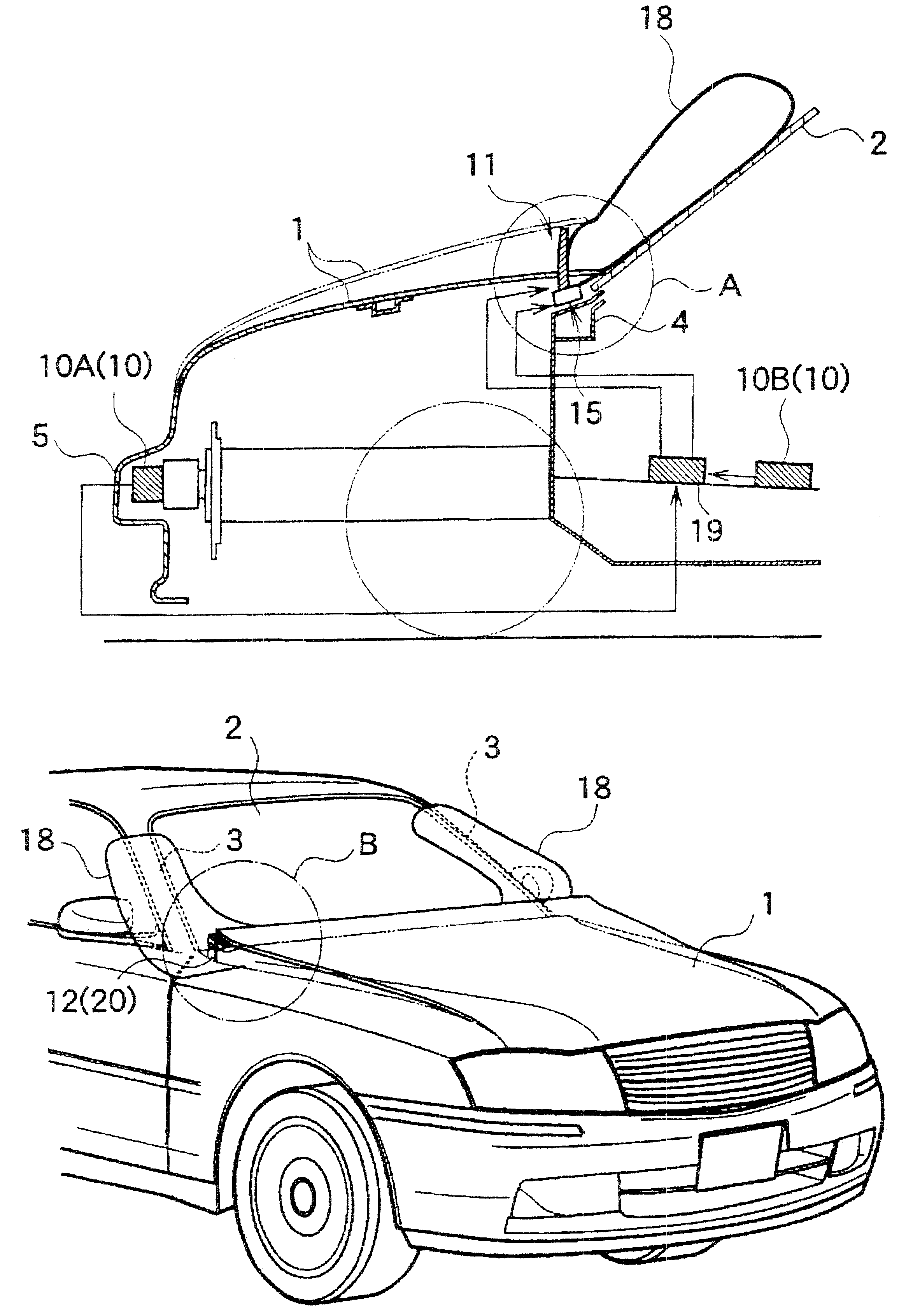
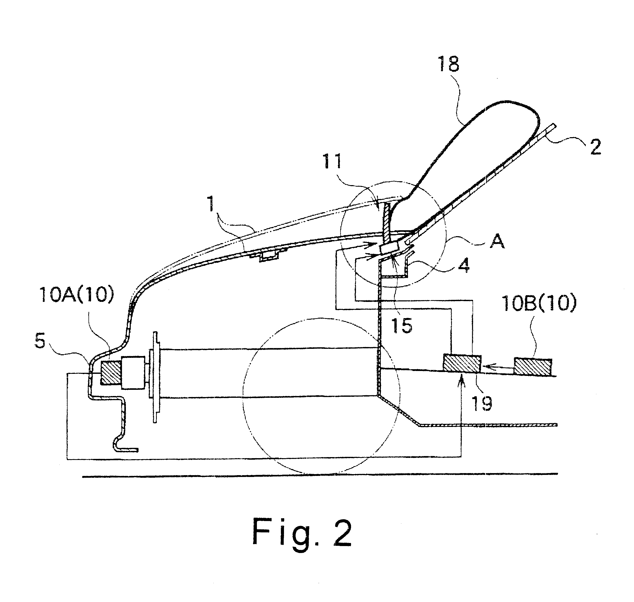
Referring now to FIGS. 12 to 14, a vehicle air bag system in accordance with a third embodiment will now be explained. In view of the similarity between the first and third embodiments, the parts of the third embodiment that are identical to the parts of the first embodiment will be given the same reference numerals as the parts of the first embodiment. Moreover, the descriptions of the parts of the third embodiment that are identical to the parts of the first embodiment may be omitted for the sake of brevity. In this embodiment, a cylindrical cover 25 covers the stay 12 that serves as the stopper 20 in the first embodiment.

The cover 25 has a bellows form that is made of an elastic material, such as plastic or rubber, with sufficient rigidity to retain its shape. The cover 25 is flexible so that it can follow the behavior of the stay 12 as shown in FIGS. 13(A) and (B). The cover 25 has a recessed part 26 formed in substantially the center of its rearwardly facing lateral surface so ...

fourth embodiment

Referring now to FIG. 15, a vehicle air bag system in accordance with a fourth embodiment will now be explained. In view of the similarity between the first and fourth embodiments, the parts of the fourth embodiment that are identical to the parts of the first embodiment will be given the same reference numerals as the parts of the first embodiment. Moreover, the descriptions of the parts of the fourth embodiment that are identical to the parts of the first embodiment may be omitted for the sake of brevity. In this embodiment, the upper guide 22 that prevents the air bag 18 from arching up in the first embodiment comprises a connecting member 27 arranged so as to span between the upper surface of the module case 16 to the vicinity of the circular folded edging part 21a on the rear end edge of the engine hood 1.

The connecting member 27 is made of an elastic material, such as plastic, with sufficient rigidity to retain its required shape. The rear end part of the connecting member is ...

fifth embodiment

Referring now to FIG. 16, a vehicle air bag system in accordance with a fifth embodiment will now be explained. In view of the similarity between the fourth and fifth embodiments, the parts of the fifth embodiment that are identical to the parts of the fourth embodiment will be given the same reference numerals as the parts of the fourth embodiment. Moreover, the descriptions of the parts of the fifth embodiment that are identical to the parts of the fourth embodiment may be omitted for the sake of brevity.

In this embodiment, a bottom guide member 29 that guides the unfolding of the bottom surface of the air bag 18 when the air bag inflates and unfolds is provided from the upper surface of the cowl top 4 to the bottom part of the front windshield 2. The bottom guide member 29 is made of plastic or a metal plate. Its bottom end is fixed to the cowl top 4 with a fastening member 30 and its upper end is forms a sloped surface that is disposed with a space between itself and the front w...


PUM


Abstract

A vehicle air bag system is provided with an air bag that inflates and unfolds to cover the entire front surface of a front pillar 3. When it is judged based on the detection operation of a collision detection device 10 that there is a risk of colliding with a pedestrian, a hood pop-up device 11 is actuated and the rear end part of the engine hood 1 moves up, widening the gap between the rear end part and the front windshield 2. Simultaneously, the air bag module 15 is actuated and the air bag 18 expands out from the gap. The air bag inflates and unfolds so as to cover the entire front surface of the front pillar 3 from the base to the upper end thereof.

Description

1. Field of the InventionThe present invention relates a vehicle air bag system. More specifically, the present invention relates to a vehicle air bag system that covers the front pillars of the vehicle body.2. Background InformationThe air bag system proposed in Laid-Open Japanese Patent Publication No. 5-281671 has an air bag module stored inside the front pillar such that the air bag inflates over the front surface of the front pillar. The air bag system proposed in Laid-Open Japanese Patent Publication No. 2000-79859 has an air bag located in the gap between the rear end edge of the engine hood and the front windshield such that the air bag inflates along the entire the rear end edge of the engine hood in the transverse direction.In view of the above, there exists a need for an air bag system which is an improvement over the above-mentioned prior art. This invention addresses this need in the prior art as well as other needs, which will become apparent to those skilled in the ar...

Claims


Application Information

Patent Timeline
Patent Type & Authority Patents(United States)
IPC IPC(8): B60R21/34B62D25/12B60R21/16B60R21/36B60R21/38B62D25/10
CPCB60R21/36B60R21/38
Inventor MIYASAKA, HIROYUKIMAKI, TETSUO
Owner NISSAN MOTOR CO LTD
Why Eureka
Try Eureka