Acoustic airspace collision detection system

a collision detection and airspace technology, applied in the direction of navigation instruments, instruments, using reradiation, etc., can solve the problems of limiting the use of uavs in the national airspace system (nas), affecting future civilian applications of uavs, and affecting the growth of the economy, etc., to achieve economic and compactness, remove the effect of platform vibration and wind nois

Active Publication Date: 2009-10-20
SCI APPL & RES ASSOCS
View PDF4 Cites 75 Cited by
  • Summary
  • Abstract
  • Description
  • Claims
  • Application Information

AI Technical Summary

Benefits of technology

[0010]An acoustic collision detection system is disclosed that comprises a digital signal processor in communication with an acoustic probe array that is mounted on exterior of an aircraft. The digital signal processor receives acoustic signals from an approaching target from the acoustic probe array and processes this data to remove noise and further assess whether the target poses a threat of collision. The digital signal processor is in communication with a flight management system of the aircraft to automatically generate and execute a clearance maneuver command based on the direction bearing of approaching air traffic, with or without operator intervention. The digital signal processor may further alert the aircraft operator of the collision danger.
[0011]The disclosed acoustic airspace collision detection system is economical and compact and provides in-flight target detection ranges of up to eight kilometers. The technology consists of an acoustic probe array and a digital signal processor which receives detected target acoustic data received by the acoustic probe array. The acoustic probe array util

Problems solved by technology

Unfortunately such growth is hampered by certain obstacles.
For example, the utilization of UAVs in the National Airspace System (NAS) is limited to operation within predetermined flight corridors and restricted access zones.
Future civilian applications of UAVs are impeded by these restrictions.
Restrictions are also placed on the use of military UAVs which are limited primarily to restricted military operational or test areas to avoid potential conflict with conventionally piloted aircraft.
However, such restrictions may limit the effectiveness of a m

Method used


Image

  • Acoustic airspace collision detection system
  • Acoustic airspace collision detection system
  • Acoustic airspace collision detection system

Examples


Embodiment Construction

[0018]The detailed description set forth below is intended as a description of the presently preferred embodiment of the invention, and is not intended to represent the only form in which the present invention may be constructed or utilized. The description sets forth the functions and sequences of steps for constructing and operating the invention. It is to be understood, however, that the same or equivalent functions and sequences may be accomplished by different embodiments and that they are intended to be encompassed within the scope of the invention.

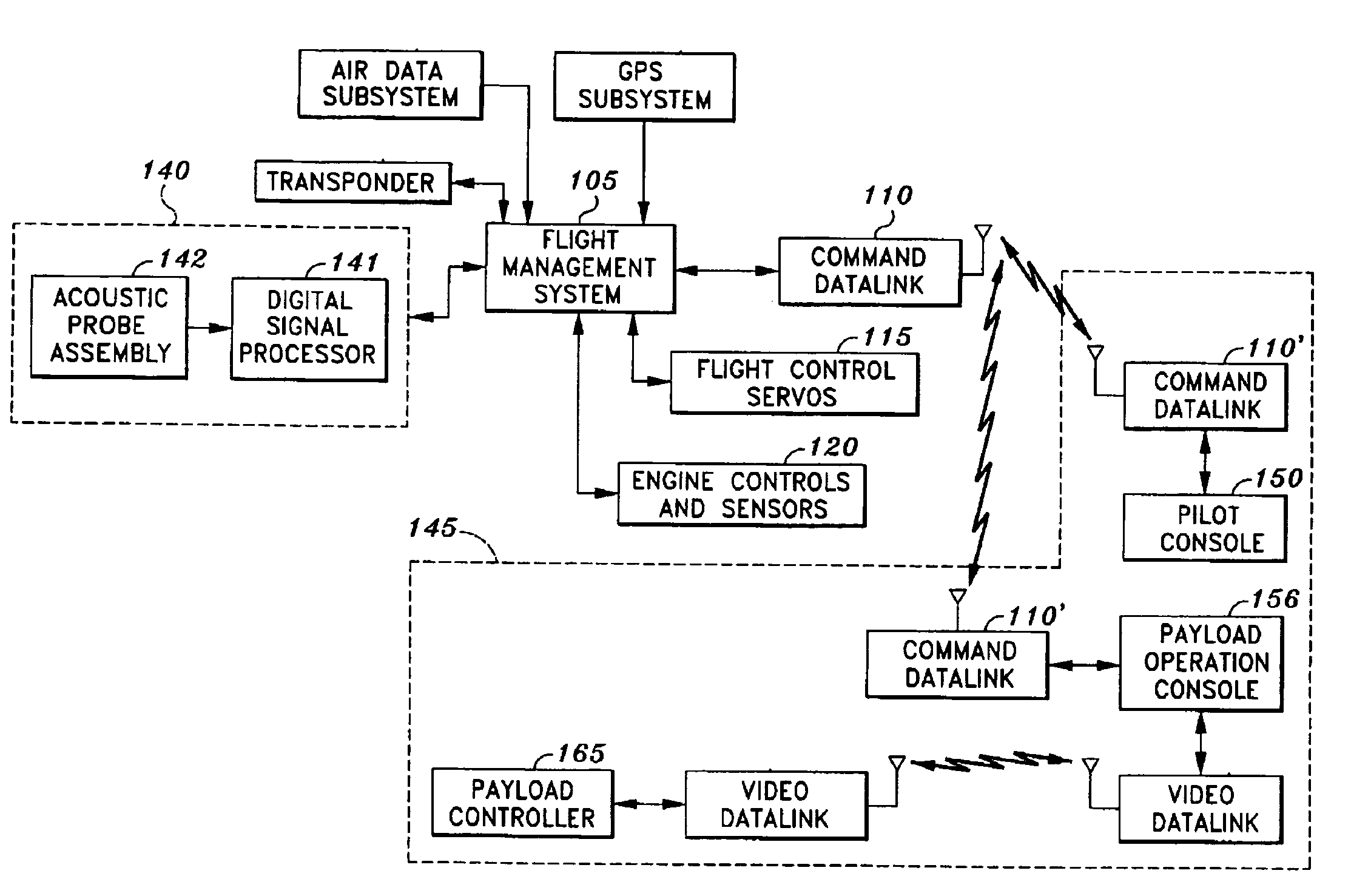
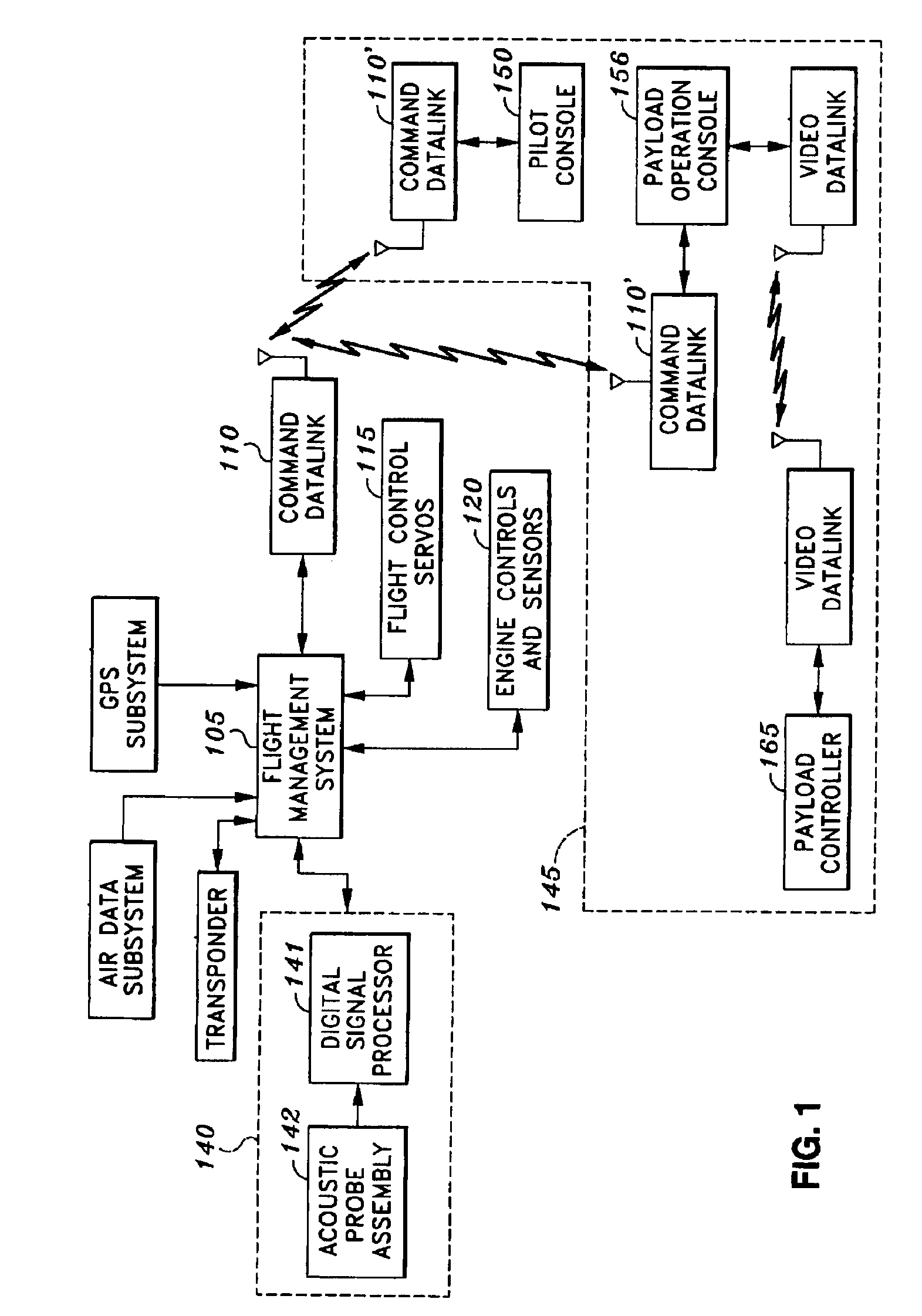
[0019]FIG. 1 is a block diagram of an exemplary integrated architecture that incorporates an acoustic collision detection system 140 into the architecture of an aircraft which is further in communication with a ground control center 145. Although FIG. 1 is directed to the incorporation of the acoustic collision detection system into a UAV, the system may be adapted for use in any type of aircraft, whether piloted or unmanned. A grou...


PUM


Abstract

An acoustic collision detection system that enables an aircraft to detect an approaching target, recognize the potential for collision and change course to maintain a safe separation distance, with or without operator invention. The acoustic collision detection system consists of an array of acoustic probes and a digital signal processor which receives acoustic data from the approaching target. The digital signal processor is configured to receive acoustic data from the array of acoustic probes; filter out noise and its own acoustic signals; extract the acoustic signals emanating from the approaching target; calculate the intensity, the bearing and the bearing angle rate of change of the approaching target, and determine whether the aircraft and the approaching target are on a potential collision course.

Description

CROSS-REFERENCE TO RELATED APPLICATIONS[0001]Not ApplicableSTATEMENT RE: FEDERALLY SPONSORED RESEARCH / DEVELOPMENT[0002]Not ApplicableBACKGROUND[0003]The present invention relates in general to an acoustic airspace collision detection system, and more particularly, to an acoustic airspace collision detection system for both piloted and unmanned aircraft that utilizes the sound generated by an approaching target to detect the direction of the target, assess the risk of collision, and automatically execute an evasive maneuver command.[0004]Unmanned aerial vehicles (UAVs) are remotely piloted or self-piloted aircraft that can carry payloads, such as cameras, sensors, and communications equipment. UAVs perform a wide variety of intelligence, reconnaissance and surveillance missions on both the modern battlefield and in an increasing array of civilian applications. UAVs are appropriate for either hazardous missions that subject a pilot to an extreme risk of danger or extended missions tha...

Claims


Application Information

Patent Timeline
IPC IPC(8): G01C23/00
CPCG08G5/045G01S3/8083Y10S367/909
Inventor CLINE, DUANE M.MILKIE, THOMAS T.
Owner SCI APPL & RES ASSOCS
Why Eureka
Try Eureka