Method for planning and executing obstacle-free paths for rotating excavation machinery

a technology of obstacle-free paths and excavation machinery, which is applied in the direction of vehicle position/course/altitude control, process and machine control, instruments, etc., can solve the problems of limited visibility and ‘blinding’ limitations, and affect the vision of humans in times of limited visibility, so as to mitigate the problems faced by operators

Active Publication Date: 2010-09-02
COMMONWEALTH SCI & IND RES ORG
View PDF29 Cites 73 Cited by
  • Summary
  • Abstract
  • Description
  • Claims
  • Application Information

AI Technical Summary

Benefits of technology

[0021]Additionally, the invention may be run on-board, that is from the machine; or off-board, that is from a remote location that is in communication with the machine via wired or wireless link. This allows mining workers other than the operator of an excavation machine to monitor and mitigate the problems faced by the operator during an excavation operation.

Problems solved by technology

However, human vision is affected in times of limited visibility, for example, at night or during periods of high atmospheric dust content.
Unfortunately, these often distract the operator from their primary task, and still suffer many of the ‘blinding’ limitations caused by dust and low-light.

Method used


Image

  • Method for planning and executing obstacle-free paths for rotating excavation machinery
  • Method for planning and executing obstacle-free paths for rotating excavation machinery
  • Method for planning and executing obstacle-free paths for rotating excavation machinery

Examples


Embodiment Construction

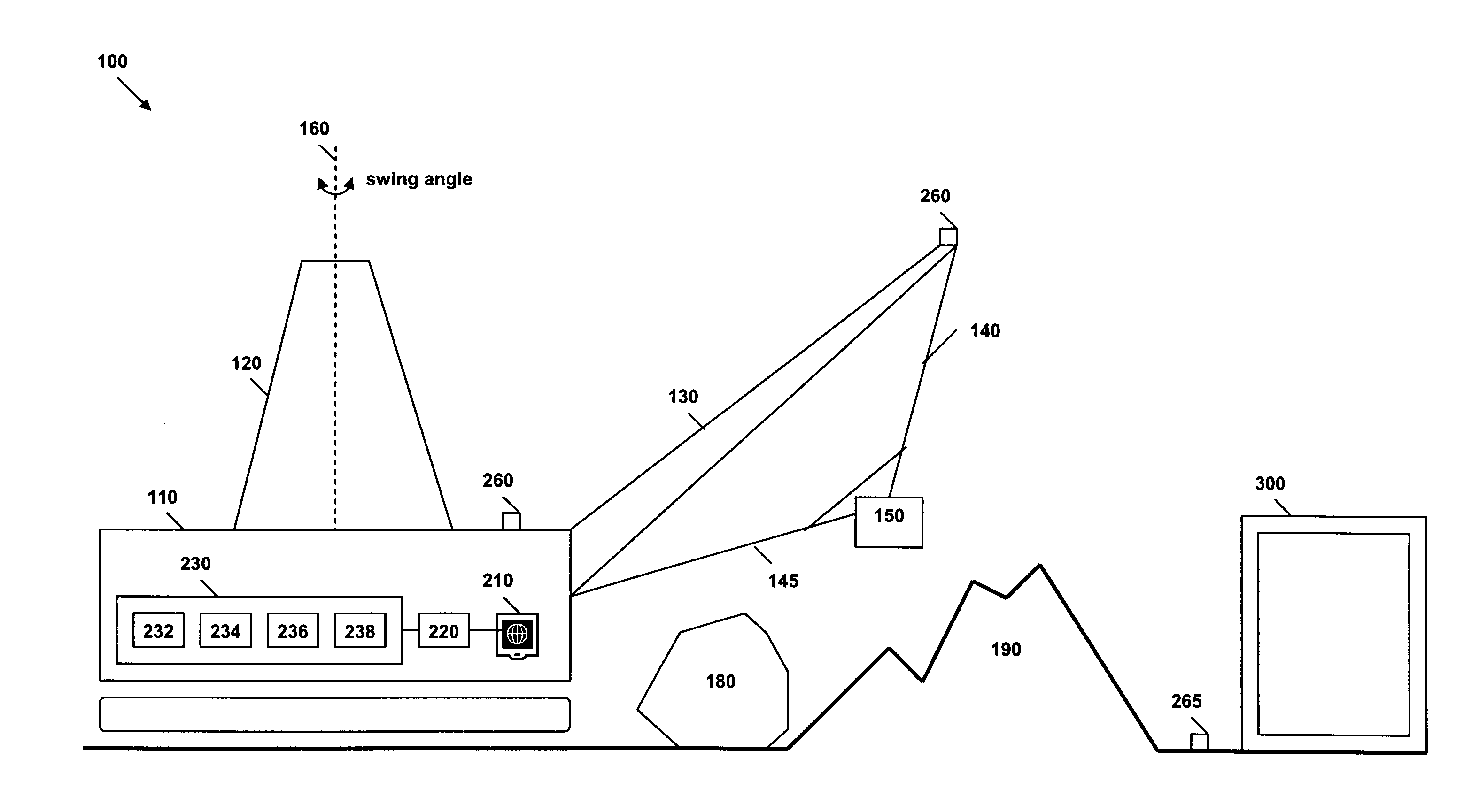
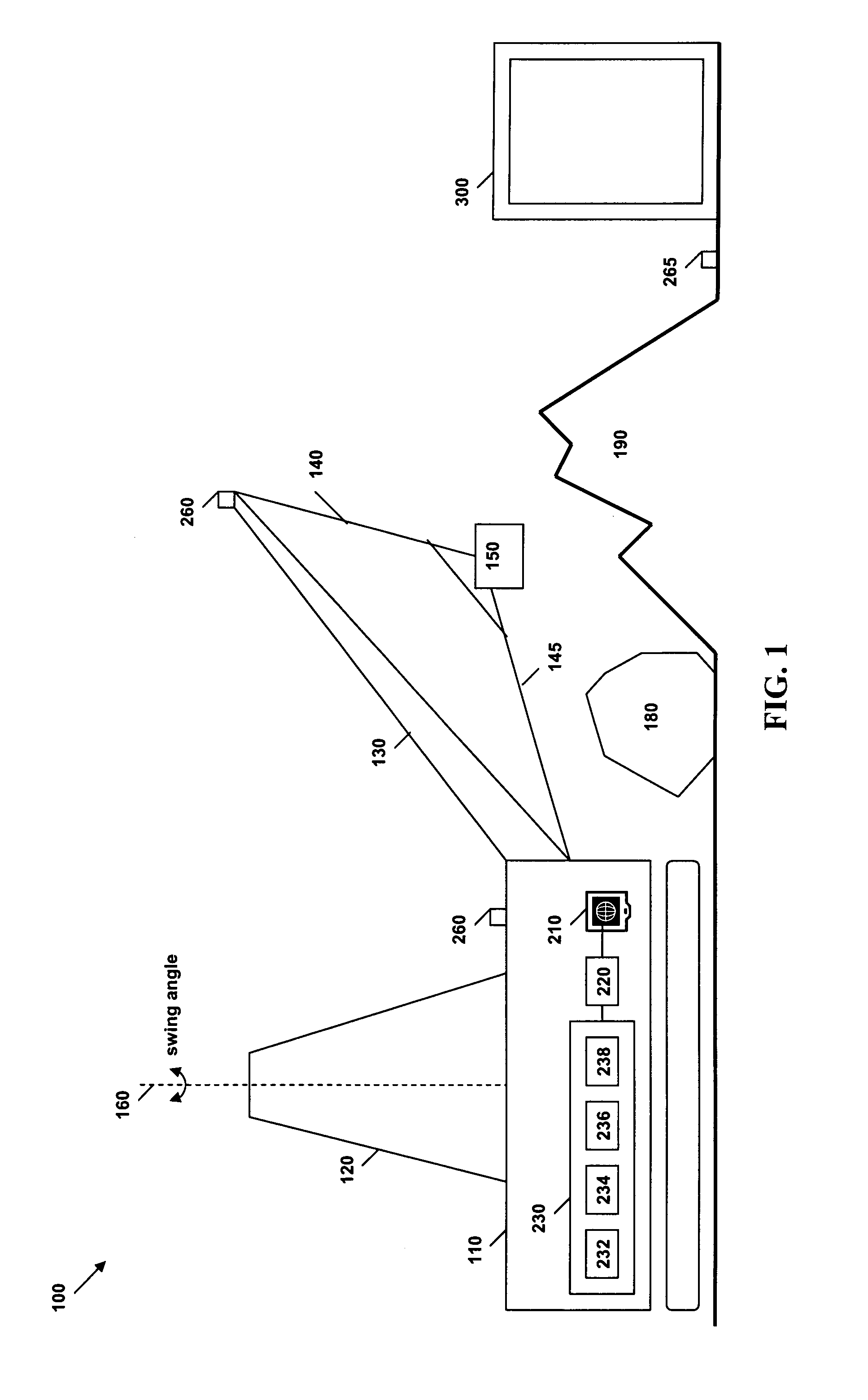
[0027]Referring first to FIG. 1, dragline 100 comprises a house 110, a mast 120, a boom 130, hoist ropes 140, drag ropes 145 and a bucket 150 suspended from the boom 130 by the hoist ropes 140. The entire dragline 100 is able to swing about its vertical axis 160. In a typical excavation cycle, the bucket 150 is first lowered to scoop material from the excavation site 190. The bucket 150 is then dragged towards the house 110 using drag ropes 145 and lifted using hoist ropes 140, filling the bucket 150. Next, the dragline 100 is swung about vertical swing axis to position the bucket 150 above the place where the material is to be dumped. The dragline 100 is typically operated using sensors and actuators under the control of code in a Programmable Logic Controller (PLC).

[0028]The swing operation typically accounts for 80% of the time of an excavation cycle. In current systems, operators rely on their knowledge of the machine's behaviour as well as visual sighting of obstacles to plan a...


PUM


Abstract

This invention concerns the control of rotating excavation machinery, for instance to avoid collisions with obstacles. In a first aspect the invention is a control system for autonomous path planning in excavation machinery, comprising: A map generation subsystem to receive data from an array of disparate and complementary sensors to generate a 3-Dimensional digital terrain and obstacle map referenced to a coordinate frame related to the machine's geometry, during normal operation of the machine. An obstacle detection subsystem to find and identify obstacles in the digital terrain and obstacle map, and then to refine the map by identifying exclusion zones that are within reach of the machine during operation. A collision detection subsystem that uses knowledge of the machine's position and movements, as well as the digital terrain and obstacle map, to identify and predict possible collisions with itself or other obstacles, and then uses a forward motion planner to predict collisions in a planned path. And, a path planning subsystem that uses information from the other subsystems to vary planned paths to avoid obstacles and collisions. In other aspects the invention is excavation machinery including the control system; a method for control of excavation machinery; and firmware and software versions of the control system.

Description

TECHNICAL FIELD[0001]This invention concerns the control of rotating excavation machinery, for instance to avoid collisions with obstacles. In its various aspects the invention includes a control system for autonomous path planning in excavation machinery; excavation machinery including the control system; a method for control of excavation machinery; and firmware and software versions of the control system.BACKGROUND ART[0002]In mining applications generally the situational awareness of the operators of large excavation machinery, such as draglines, shovels and excavators, is very important. Current best practice for obstacle avoidance is centred on the training of the operators. Operators primarily rely on the visual sighting of obstacles, and their knowledge of a machine's behaviour to plan safe and effective paths for the machine's operation.[0003]However, human vision is affected in times of limited visibility, for example, at night or during periods of high atmospheric dust co...

Claims


Application Information

Patent Timeline
Patent Type & Authority Applications(United States)
IPC IPC(8): G06F7/00G06T17/05
CPCG05D1/024G05D1/0246G05D1/0257G05D1/0274E02F9/265G05D2201/0202E02F9/2045E02F9/2033E02F9/262G05D1/0278
Inventor DUNBABIN, MATTHEWCORKE, PETERWINSTANLEY, GRAEMEUSHER, KANE
Owner COMMONWEALTH SCI & IND RES ORG
Why Eureka
Try Eureka