Motor
A motor and main body technology, applied in the field of motors, can solve problems such as coil wire breakage, coil wire breakage, etc.
- Summary
- Abstract
- Description
- Claims
- Application Information
AI Technical Summary
Problems solved by technology
Method used
Image
Examples
Embodiment approach 1
[0055] the whole frame
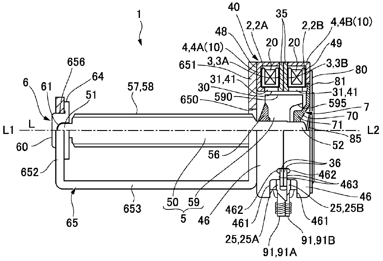
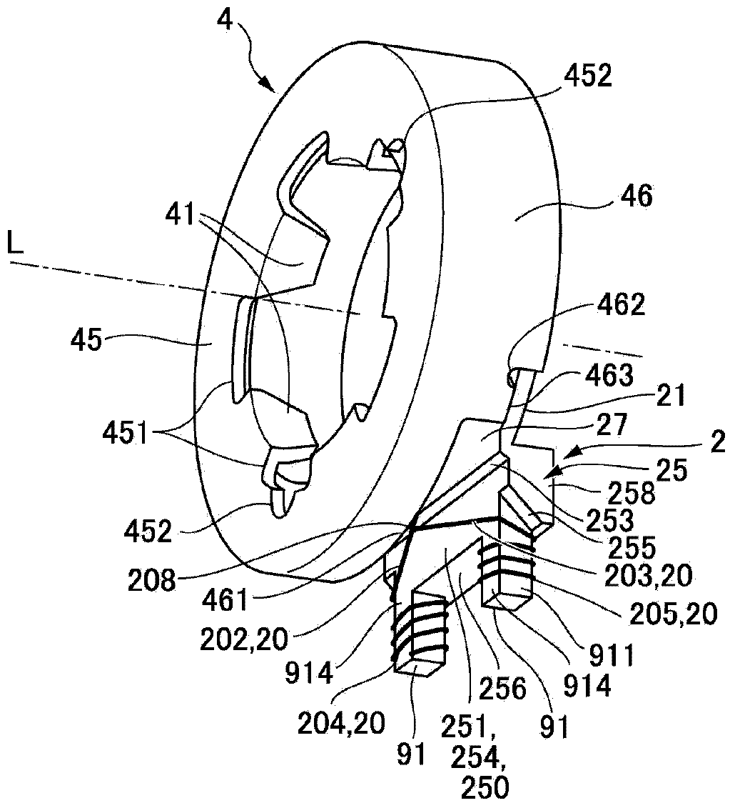
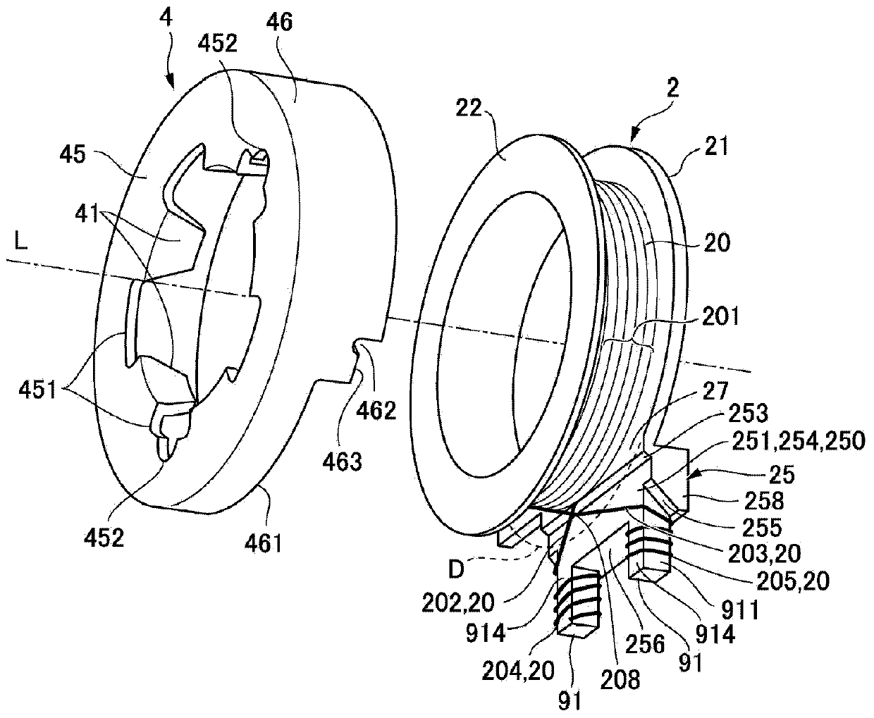
[0056] figure 1 It is a half sectional view of the motor according to Embodiment 1 of the present invention. figure 1 The illustrated motor 1 is a stepping motor used for driving an optical head in optical disc drive devices such as DVD and Blu-ray Disc, and has a cylindrical stator 40 . The stator 40 has a structure in which an A-phase stator group and a B-phase stator group are arranged to overlap each other in the motor axis direction L. As shown in FIG. Therefore, in the stator 40 , two ring-shaped bobbins 2 (the first bobbin 2A and the second bobbin 2B) around which the coil wire 20 is wound are overlapped in the motor axis direction L, and The inner stator core 3 and the outer stator core 4 are stacked on top of each other. More specifically, in the first bobbin 2A, the ring-shaped inner stator core 3A and the outer stator core 4A with a U-shaped cross section are stacked on both sides of the motor axis direction L, and the second bobbin In 2...
Embodiment approach 2
[0090] Figure 6 It is a top view of bobbin 2 of motor 1 according to Embodiment 2 of the present invention seen from the second edge portion 22 side. In addition, in Figure 6 In , a state in which the second edge portion 22 is partially cut away is shown. In addition, since the basic configuration of the present embodiment is the same as that of the first embodiment, the same reference numerals are assigned to the common parts and their descriptions are omitted.
[0091] In the first embodiment, in the bobbin 2 , in the surface 251 of the terminal block 25 on the body portion 23 side, the entire radially outer region including the coil wire winding region 250 is the lower region 254 . In contrast, in this embodiment, if Figure 6 As shown, in the outer region of the surface 251 on the side of the body part 23 of the terminal block 25 that overlaps with the second edge part 22 in the motor axis direction L, the winding parts 202 and 203 of the coil wire 20 are aligned with...
Embodiment approach 3
[0094] Figure 7 It is a sectional view of bobbin 2 of motor 1 according to Embodiment 3 of the present invention. In addition, since the basic structure of this embodiment is the same as that of Embodiment 1, the same code|symbol is attached|subjected to a common part, and description is abbreviate|omitted.
[0095] Such as Figure 7As shown, in this embodiment as well in Embodiment 1, in the bobbin 2 , the entire radially outer region of the surface 251 on the side of the main body 23 of the terminal block 25 becomes the lower region 254 . Regarding the above-mentioned bobbin 2, in Embodiment 1, the terminal 91 is a resin integrated with the terminal base 25, but in this embodiment, the terminal 91 is a terminal pin made of metal whose base part is held on the terminal base 25. . Therefore, the surface 914 of the terminal 91 on the side of the main body 23 is located on the opposite side of the main body 23 from the coil wire winding region 250 in the motor axis direction...
PUM
 Abstract
Description
Claims
Application Information
 - R&D
- Intellectual Property
- Life Sciences
- Materials
- Tech Scout
- Unparalleled Data Quality
- Higher Quality Content
- 60% Fewer Hallucinations
Browse by: Latest US Patents, China's latest patents, Technical Efficacy Thesaurus, Application Domain, Technology Topic, Popular Technical Reports.
© 2025 PatSnap. All rights reserved.Legal|Privacy policy|Modern Slavery Act Transparency Statement|Sitemap|About US| Contact US: help@patsnap.com


