
Improved QoS dynamic configuration method

A technology of dynamic configuration and rules, applied in digital transmission systems, electrical components, transmission systems, etc., can solve the problems of bloated equipment, high cost, and no hardware forwarding bandwidth, etc., to ensure equipment security and good control. Network, the effect of enhancing security

Inactive Publication Date: 2014-05-14
CHONGQING JINMEI COMM
View PDF2 Cites 6 Cited by
  • Summary
  • Abstract
  • Description
  • Claims
  • Application Information

AI Technical Summary

Problems solved by technology

However, with the increasing demands of users on network performance and the existence of many security problems in the network, many complex functions are added to the architecture of switching devices, resulting in more and more bloated devices and more room for performance improvement. The smaller the size, the greater the challenge to the QoS service
In view of the current status of switching networks, some organizations have proposed some new ideas and even manufactured devices to solve these problems, such as OpenFlow switches. However, traditional switching devices are generally used in the current network. means replacing old equipment with new equipment, which is undoubtedly very expensive
However, the existing QoS service configuration method, in terms of performance, static configuration cannot provide sufficient performance guarantee for newly accessed data with specific requirements, although dynamic configuration can provide dynamic QoS services for newly accessed data, but it is difficult to complete This service action is basically software forwarding, which cannot reach the speed of hardware forwarding, nor does it have the bandwidth of hardware forwarding; and in terms of security, whether it is static or dynamic configuration, it is necessary to directly operate inside the device. It means that equipment manufacturers need to publish the internal structure, which is not in the interests of equipment manufacturers

Method used

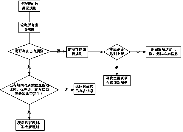

Image

  • Improved QoS dynamic configuration method
  • Improved QoS dynamic configuration method
  • Improved QoS dynamic configuration method

Examples


Embodiment Construction

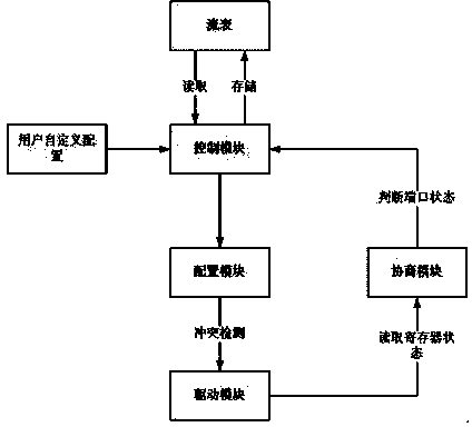
[0011] In order to realize this solution, the control module, flow table, configuration module, driver module, and negotiation module need to cooperate with each other. The functions of these modules are as follows:

[0012] 1. Control module:

[0013] (1) During the initialization process, read the data flow rules stored in the flow table and send them to the configuration module;

[0014] (2) Receive the data flow rules added by users and the new data flow rules sent by the negotiation module, and send the rules to the flow table, so as to control the flow table;

[0015] (3) Receive the data flow that does not match any flow table entry, read the forwarding purpose of the data flow, and send it to the corresponding exit, otherwise discard it directly.

[0016] 2. Flow table:

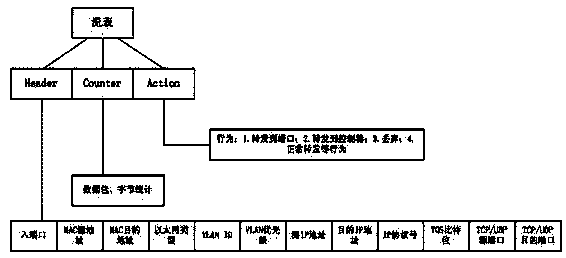
[0017] Multiple flow entries are stored in the flow table, and each flow entry corresponds to a forwarding rule, thus forming multiple forwarding rules. The data flow entering the switching network...


PUM


Abstract

The invention provides an improved QoS dynamic configuration implementation method suitable for a traditional switching network in the existing mode that a switch and a router are adopted at the same time. The method comprises the steps that (1) a control module initializes a rule and controls a flow table; (2) the flow table stores an ACL rule; (3) a configuration module judges and detects the rule which is issued by the control module; (4) a drive module enables the data flow rule which is issued by the configuration module to take effect and monitors the state of an interface in real time; (5) a consultation module judges the state of interface data which are sent by the drive module and informs the control module to conduct corresponding action. The improved QoS dynamic configuration implementation method has the advantages that on the premise that the structure of the traditional switching network is not changed, intelligent and dynamic Qos configuration is achieved, a user can define the rule at the same time, and therefore labor and material sources are saved; besides, a device manufacturer just needs to provide the interface, the inner structure does not need to be opened, the user can meet the QoS demand without operating the interior of a device, as a result, the safety of the device is guaranteed, and the benefit requirement of the device manufacturer can be met.

Description

technical field [0001] The invention relates to an improved QoS dynamic configuration method in the existing switching network. Background technique [0002] In the existing switching network, QoS is to set a variety of forwarding rules to monitor the data traffic transmitted in the network in real time, plan bandwidth, dynamically modify the priority, and smooth shape the data traffic to meet the user's requirements for data service quality. and security needs. However, with the increasing demands of users on network performance and the existence of many security problems in the network, many complex functions are added to the architecture of switching devices, resulting in more and more bloated devices and more room for performance improvement. The smaller the value, the greater the challenge to the QoS service. In view of the current status of switching networks, some organizations have proposed some new ideas and even manufactured devices to solve these problems, such ...

Claims


Application Information

Patent Timeline
IPC IPC(8): H04L12/917H04L12/927H04L47/76H04L47/80
Inventor 郑直王亚昕李世钊汤程陈量
Owner CHONGQING JINMEI COMM
Learn More