
Over-voltage and under-voltage protection circuit, electronic ballast and over-voltage and under-voltage detection method thereof

An electronic ballast, overvoltage and undervoltage technology, applied in the field of lighting, can solve problems such as electronic ballasts not working properly

Active Publication Date: 2014-05-14
FUJIAN RAYNEN TECH
View PDF5 Cites 3 Cited by
  • Summary
  • Abstract
  • Description
  • Claims
  • Application Information

AI Technical Summary

Problems solved by technology

[0010] 1. After the fuse is activated, manual processing is required;
[0011] 2. After the fuse operates, when the grid voltage returns to normal, the electronic ballast cannot work normally;

Method used


Image

  • Over-voltage and under-voltage protection circuit, electronic ballast and over-voltage and under-voltage detection method thereof
  • Over-voltage and under-voltage protection circuit, electronic ballast and over-voltage and under-voltage detection method thereof
  • Over-voltage and under-voltage protection circuit, electronic ballast and over-voltage and under-voltage detection method thereof

Examples


Embodiment Construction

[0030] The following description will be made in conjunction with the accompanying drawings and specific implementation manners.

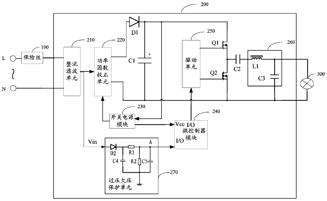
[0031] refer to figure 2 , figure 2 It is a structural schematic diagram of an embodiment of the electronic ballast of the present application. Compared with the prior art, the electronic ballast 200 of this embodiment adds an overvoltage and undervoltage protection unit 270, and the overvoltage and undervoltage protection unit 270 includes: a diode D2, a first capacitor C4, a first resistor R1 and a second Two resistors R2. One terminal of the overvoltage and undervoltage protection unit 270 is connected to the output terminal Vin of the rectification and filtering unit 210 , and the other terminal is connected to the input terminal of the microcontroller unit 240 .

[0032] The anode of the diode D2 is used to connect the output terminal Vin of the rectification and filtering unit 210, and the cathode is connected to one end of the first cap...


PUM


Abstract

The application discloses an over-voltage and under-voltage protection circuit comprising a diode (D2), a first capacitor (C4), a first resistor (R1) and a second resistor (R2). The diode (D2) detects a maximum voltage after rectification to realize peak value sampling; the first capacitor (C4) filters a ripple wave of an input voltage after the peak value sampling; the first resistor (R1) and the second resistor (R2) carry out voltage division on the input voltage after the ripple wave filtering and a division voltage is outputted to an input terminal of a microprocessor at the common terminal of the first resistor (R1) and the second resistor (R2). In addition, the application also discloses an electronic ballast and over-voltage and an under-voltage detection method thereof. According to the scheme, because of arrangement of the over-voltage and under-voltage protection circuit, the effect that automatic lighting can be realized without the need of manual processing after the power grid voltage is recovered can be realized; and the impact on surge currents of the power grid and the electronic ballast when the power-on situation is started again after the low-voltage recovery is realized can be reduced.

Description

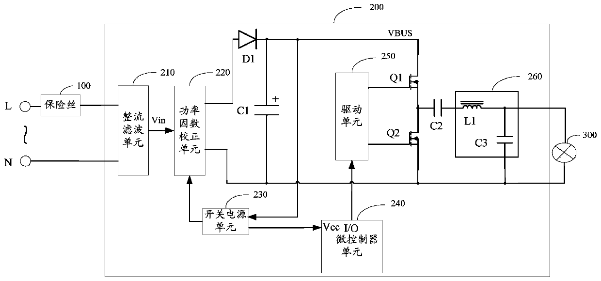
technical field [0001] The application relates to the lighting field, in particular to an overvoltage and undervoltage protection circuit, an electronic ballast and an overvoltage and undervoltage detection method thereof. Background technique [0002] At present, in the lighting system, a fuse of appropriate specification is usually connected in series with the power input terminal of the electronic ballast. When the rated current of the fuse is reached, the fuse operates to protect the electronic ballast. [0003] see figure 1 , figure 1 It is a structural schematic diagram of an implementation mode of the lighting system in the prior art. [0004] The lighting system includes sequentially connected: a fuse 100, an electronic ballast 200, and a load 300, wherein the electronic ballast 200 includes: a rectification and filtering unit 210, a power factor correction (Power Factor Correction, PFC) unit 220, a switching power supply unit 230 , a microcontroller unit 240 , a...

Claims


Application Information

Patent Timeline
Patent Type & Authority Applications(China)
IPC IPC(8): H05B41/285
CPCY02B20/00
Inventor 刘茂龙李仁庆王开伟
Owner FUJIAN RAYNEN TECH
Learn More