
Respirator tube fixing frame used for sickbed

A pipeline fixing and ventilator technology, which is applied in the field of medical equipment, can solve the problems of unfavorable patient rescue, pulling, violent shaking of the breathing pipeline, etc., and achieve good vibration reduction effect, effective and fast adjustment, and enhanced stability.

Inactive Publication Date: 2014-05-21
THE FIRST AFFILIATED HOSPITAL OF HENAN UNIV OF SCI & TECH
View PDF13 Cites 6 Cited by
  • Summary
  • Abstract
  • Description
  • Claims
  • Application Information

AI Technical Summary

Problems solved by technology

[0004] First, the stability of the cantilever that comes with the ventilator is poor, and there is only one support point. Under the action of moving the ventilator or other external forces, it is very easy to cause severe shaking, displacement, and pulling of the breathing tube, which will affect the ventilator’s performance. The normal oxygen delivery of the patient affects the smooth progress of the rescue work, and even endangers the life of the patient in severe cases;
[0005] Second, the cantilever that comes with the ventilator is not easy to adjust. The cantilever of most ventilators is composed of three to four sections of mechanical arms. The direction and height of the breathing tube at the end are adjusted. Since the cantilever has multiple adjustment parts, it is difficult to adjust to a suitable direction and angle at one time, and repeated adjustments are required. Therefore, it takes a lot of time to adjust the breathing tube. It is not conducive to the rescue of patients;
[0006] Third, some ventilators can generate large vibrations. The cantilever is used to fix the breathing tube. Breathing and the vibration generated can be transmitted to the patient through the breathing tube, making the patient feel uncomfortable and even affecting the use of the ventilator.

Method used


Image

  • Respirator tube fixing frame used for sickbed
  • Respirator tube fixing frame used for sickbed
  • Respirator tube fixing frame used for sickbed

Examples


Embodiment Construction

[0026] The present invention will be further described through specific embodiments below in conjunction with the accompanying drawings.

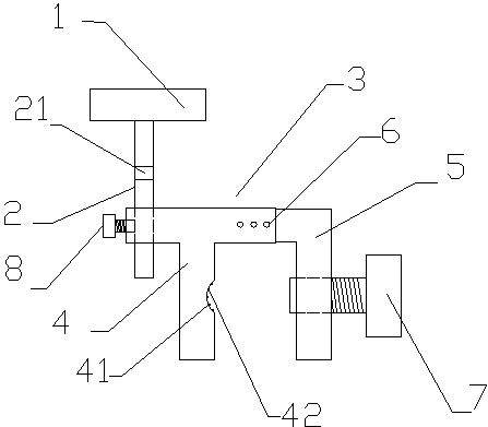
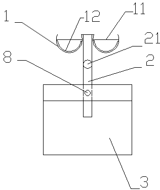
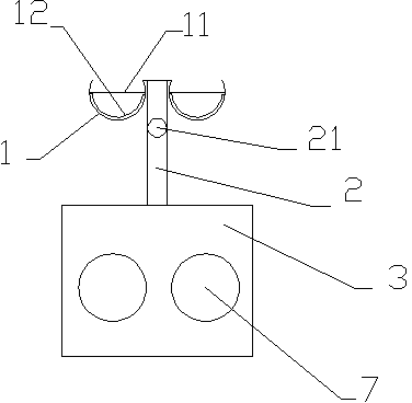
[0027] As shown in the figure, a ventilator pipe fixing frame for a hospital bed includes an arc-shaped bracket 1 with a pillar 2 and a base 3. The base 3 is composed of a part I4 and a part II5, and the part I4 and part II5 are connected by a spring. The clips are clamped in different small holes 6 to form a clamping part with adjustable width, which is clamped and fixed on the hospital bed by the top wire I7. The clamping part is provided with an arc-shaped groove 41 for clamping on the guardrail of the hospital bed. In addition, a plurality of ribs 42 made of flexible materials are provided in the arc-shaped groove 41, and the arc-shaped bracket 1 for carrying the ventilator pipeline is inserted into the opening of the base 3 through the pillar 2, and is connected by the top wire II 8 fixed, the pillar 2 is divided into upper and lower p...


PUM


Abstract

A respirator tube fixing frame used for a sickbed comprises a base and a cambered surface bracket with a supporting column. The base is composed of a first component and a second component, the first component and the second component are connected through a spring clamping lock to form a clamping part with the width adjustable, and the clamping part is clamped and fixed to the sickbed through a first jackscrew. The cambered surface bracket used for bearing a respirator tube is inserted in a hole formed in the base through the supporting column and fixed through a second jackscrew. The supporting column is divided into an upper part and a lower part which are connected through a rotary connecting device. Compared with a cantilever fixing mode of a respirator, the respirator tube can be effectively supported and fixed, the respirator tube fixing frame has good stability and can effectively avoid the phenomenon of shift of the respirator tube caused by vibration of the respirator and action of external force, the position of the respirator tube can be adjusted easily and conveniently, time and labor are saved, moreover, the respirator tube fixing frame is small in size and occupied space and favorable for operation of medical workers, and the working efficiency of the medical workers is improved.

Description

technical field [0001] The invention relates to the technical field of medical devices, in particular to a ventilator pipe fixing frame for a hospital bed. Background technique [0002] When rescuing patients with respiratory failure, invasive ventilators are often used clinically to maintain the patient's breathing. An invasive ventilator is mainly composed of a ventilator and a pipeline system for delivering gas. The ventilator is located on the side of the bed when in use, and the breathing tube system connects the ventilator to the patient. [0003] The composition of the breathing tube system is relatively complicated, consisting of multiple silicone breathing tubes, heating tanks, water collection cups, etc. The length and weight of the silicone breathing tube are relatively large, and it is supported by a cantilever that comes with the ventilator when in use. There are following deficiencies in this supporting device: [0004] First, the stability of the cantilever...

Claims


Application Information

Patent Timeline
Patent Type & Authority Applications(China)
IPC IPC(8): A61G7/05A61M16/00
Inventor 李波焦瑞娟芦延峰王华申哲
Owner THE FIRST AFFILIATED HOSPITAL OF HENAN UNIV OF SCI & TECH
Learn More