
Production clamping device for mechanical accessories

A technology for clamping devices and mechanical accessories, applied in the direction of workpiece clamping devices, manufacturing tools, etc., can solve the problems of not being able to adjust the height of the clamping position, increase the probability of damage to accessories, and affect the tightness of clamping, etc., to achieve enhanced stability and firmness, enhanced protection, and the effect of expanding the bearing surface

Inactive Publication Date: 2020-08-14
JIAXING UNIV
View PDF8 Cites 1 Cited by
  • Summary
  • Abstract
  • Description
  • Claims
  • Application Information

AI Technical Summary

Problems solved by technology

[0004] 1. The existing clamping device for accessory production, when in use, because the clamping part cannot change the outer profile of the mechanical component itself, which affects the tightness of the clamping, it is prone to unstable clamping, and increases the damage to the accessory probability;
[0005] 2. The placement plate of the existing clamping device does not have the function of up and down adjustment, which affects the clamping efficiency, and the bearing area is small, so it cannot be placed for large-volume mechanical parts, which has certain limitations;
[0006] 3. The existing clamping device itself cannot adjust the height of the clamping position, which reduces the overall flexibility, and the overall inconvenience is fixed according to the location of use, which reduces the applicability

Method used


Image

  • Production clamping device for mechanical accessories
  • Production clamping device for mechanical accessories
  • Production clamping device for mechanical accessories

Examples


Embodiment Construction

[0031] The following will clearly and completely describe the technical solutions in the embodiments of the present invention with reference to the accompanying drawings in the embodiments of the present invention. Obviously, the described embodiments are only some, not all, embodiments of the present invention. Based on the embodiments of the present invention, all other embodiments obtained by persons of ordinary skill in the art without making creative efforts belong to the protection scope of the present invention.

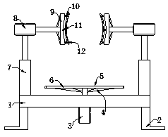
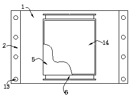
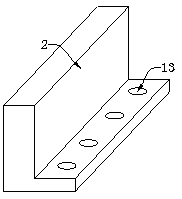
[0032] like Figure 1-5 Shown, a kind of clamping device for the production of mechanical parts proposed by the present invention includes a base plate 1, the bottom surface of the base plate 1 is symmetrically fixed with a base 2, and a first cylinder 3 is installed at the middle position of the bottom surface of the base plate 1. The first cylinder The output shaft of 3 runs through the bottom plate 1 and extends to its top, the outer wall of the telescopic ...


PUM


Abstract

The invention belongs to the technical field of mechanical accessory production, and particularly relates to a production clamping device for mechanical accessories. The production clamping device comprises a bottom plate, bases are symmetrically and fixedly arranged on the bottom face of the bottom plate, a first air cylinder is installed in the middle of the bottom face of the bottom plate, an output shaft of the first air cylinder penetrates through the bottom plate and extends to the top of the bottom plate, connecting rods are symmetrically installed on the outer side wall of a telescopicshaft of the first air cylinder, two abutting plates clamp a mechanical accessory, each abutting plate has good deformation force due to the elastic effect generated by multiple compression springs inside the corresponding containing cavity so that the abutting plates can change along with the outline of the accessory, and the abutting plates can be attached to the accessory easily; meanwhile, the friction force between the abutting plates and the accessory is increased through connecting plates and multiple grooves, the stability and firmness are enhanced, and the accessory is not prone to slide and falling; and under the action of first springs and second springs, the abutting plates have certain rebound resilience, so that clamping is prevented from being too tight, damage to the accessory is reduced, and protection is enhanced.

Description

technical field [0001] The invention belongs to the technical field of mechanical parts production, and in particular relates to a production clamping device for mechanical parts. Background technique [0002] Various parts and accessories for replacement and maintenance of construction machinery, production equipment, and transportation equipment, such as crankshafts, pistons, bearings, etc., in the accounting of construction enterprises, set up the "machinery parts" account to account for the mechanical parts in the inventory. , it is necessary to perform clamping steps on mechanical parts in order to complete subsequent operations. [0003] There are following problems in existing technology: [0004] 1. The existing clamping device for accessory production, when in use, because the clamping part cannot change the outer profile of the mechanical component itself, which affects the tightness of the clamping, it is prone to unstable clamping, and increases the damage to th...

Claims


Application Information

Patent Timeline
Patent Type & Authority Applications(China)
IPC IPC(8): B25B11/00
CPCB25B11/00
Inventor 赵天爱杨超黄风立陈如清朱荷蕾
Owner JIAXING UNIV
Learn More